What is the main thread? Types of threads and their characteristics
- unit of diameter (metric, inch, modular, pitch thread)
- location on the surface (external and internal thread)
- direction of movement of the helical surface (right, left);
- number of passes (single- and multi-pass), for example, two-pass, three-pass, etc.;
- profile (triangular, trapezoidal, rectangular, round, etc.);
- the forming surface on which the thread is located (cylindrical thread and conical thread);
- purpose (fastening, fastening and sealing, chassis, etc.).
Basic thread parameters and units of measurement
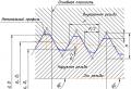
Diagram of a cylindrical thread.

Tapered thread diagram.
Metric thread- with pitch and basic thread parameters in millimeters.
Inch thread- all thread parameters are expressed in inches (most often indicated by a double stroke placed immediately after the numerical value, for example, 3" = 3 inches), thread pitch in fractions inches(inch = 2.54 cm). For inch pipe threads, the size in inches conventionally characterizes the clearance in the pipe, and the outer diameter is, in fact, significantly larger.
Metric and inch threads are used in threaded connections and screw drives.
Modular thread- thread pitch is measured module(m). To get the size in millimeters, just multiply the module by pi ().
Pitch thread- thread pitch is measured in pitches(p"). To obtain the numerical value (in inches), it is enough to divide pi () by pitch.
Modular and pitch threads are used when cutting the worm of a worm gear. The coil profile of a modular worm can look like Archimedean spiral, involutes of a circle, extended or shortened involute And trapezoids.
- step (P)- the distance between the same side sides of the profile, measured in fractions meters, in fractions inches or number of threads per inch is the denominator of a common fraction whose numerator is an inch. Expressed as a natural number (for example; 28, 19, 14, 11);
- outer diameter (D, d), the diameter of the cylinder described around the tops of the external thread (d) or the valleys of the internal thread (D);
- average diameter (D 2, d 2), the diameter of the cylinder, the generatrix of which intersects the thread profile in such a way that its segments formed at the intersection with the groove are equal to half the nominal thread pitch;
- internal diameter (D 1, d 1), the diameter of the cylinder inscribed in the depressions of the external (d 1) or the top of the internal thread (D 1);
- stroke (P h) the magnitude of the relative movement of the initial midpoint along the helical line of the thread at an angle of 360°
where is the number of visits;
Thread types
Metric, M
Widely used with nominal diameters from 1 to 600 mm and pitches from 0.25 to 6 mm. The profile is an equilateral triangle (vertex angle 60°) with a theoretical profile height Н=0.866025404Р. All profile parameters are measured in millimeters.
Standards:
- GOST 24705-2004 (ISO 724:1993)- Metric thread. Basic dimensions.
- GOST 9150-2002- Basic norms of interchangeability. Metric thread. Profile.
- GOST 8724-2002- Basic norms of interchangeability. Metric thread. Diameters and steps.
- ISO 965-1:1998- Metric ISO threads for general purpose. Tolerances. Part 1. Principles and main characteristics.
- ISO 965-2:1998- Metric ISO threads for general purpose. Tolerances. Part 2. Limit dimensions of threads for general purpose bolts and nuts. Average accuracy class.
- ISO 965-3:1998- Metric ISO threads for general purpose. Tolerances. Part 3. Deviations for structural threads.
- ISO 965-4:1998- Metric ISO threads for general purpose. Tolerances. Part 4: Dimensions for hot-dip galvanized external screw threads for assembly with internal screw threads tapped to tolerance H or G after galvanization.
- ISO 965-5:1998- Metric ISO threads for general purpose. Tolerances. Part 5. Limit dimensions for internal screw threads of screws for assembly with external screw threads hot-dip galvanized, with a maximum tolerance position size h before galvanizing.
- ISO 68-1- General purpose ISO screw threads. Main profile. Metric thread.
- ISO 261:1998- ISO metric threads for general purpose. General form.
- ISO 262:1998- ISO metric general purpose threads. Selected sizes for screws, bolts and nuts.
- BS 3643- ISO metric screw threads.
- DIN 13-12-1988- Metric ISO basic and precision threads with diameters from 1 to 300 mm. Choice of diameters and pitches.
- ANSI B1.13M, ANSI B1.18M- Metric thread M with a profile based on the ISO 68 standard.
Symbol: the letter M (metric), the numerical value of the nominal thread diameter (d, D in the diagram, it is also the outer diameter of the thread on a bolt) in millimeters, the numerical value of the pitch (for fine-pitch threads) (P in the diagram) and the letters LH for left-hand threads . For example, a thread with a nominal diameter of 16 mm with a coarse pitch is designated as M16; thread with a nominal diameter of 36 with a fine pitch of 1.5 mm - M36x1.5; the same diameter and pitch but left-hand thread M36x1.5LH.
| M0.25 | 0.075 | M1.1 | 0.25 | M5 | 0.8 | M17 | 2 |
|---|---|---|---|---|---|---|---|
| M0.3 | 0.08 | M1.2 | 0.25 | M5.5 | 0.8 | M18 | 2.5 |
| M0.35 | 0.09 | M1.4 | 0.3 | M6 | 1 | M20 | 2.5 |
| M0.4 | 0.1 | M1.6 | 0.35 | M7 | 1 | M22 | 2.5 |
| M0.45 | 0.1 | M1.8 | 0.35 | M8 | 1.25 | M24 | 3 |
| M0.5 | 0.125 | M2 | 0.4 | M9 | 1.25 | M25 | 3 |
| M0.55 | 0.125 | M2.2 | 0.45 | M10 | 1.5 | M26 | 3 |
| M0.6 | 0.15 | M2.5 | 0.45 | M11 | 1.5 | M27 | 3 |
| M0.7 | 0.175 | M3 | 0.5 | M12 | 1.75 | M28 | 3 |
| M0.8 | 0.2 | M3.5 | 0.6 | M14 | 2 | M30 | 3.5 |
| M0.9 | 0.225 | M4 | 0.7 | M15 | 2 | M32 | 3.5 |
| M1 | 0.25 | M4.5 | 0.75 | M16 | 2 |
Metric tapered, MK
Standard: GOST 6042-83 Edison thread is round. Profiles, dimensions and limits.
Thread symbol: Letter E, thread number, if the thread for non-metallic elements is the letter N separated by a slash (/) and the GOST number, for example E 27 GOST 6042-83 or E 27/N GOST 6042-83.
Metric EG-M
Inch cylindrical UTS
UTS (Unified Thread Standard) - inch cylindrical thread, widely used in the USA and Canada. Apex angle 60°, theoretical profile height H=0.866025P. Depending on the step, it is divided into: UNC (Unified Coarse); UNF (Unified Fine); UNEF (Unified Extra Fine); 8UN; UNS (Unified Special). Extremely widespread UNC 1/4 (1/4"x1.25mm). It is present in the mount of almost all modern digital and film photo and video cameras (as well as tripods) of small format. Its parameters are D=6.35mm, D 1 =4.975mm, pitch 20 threads per inch (1.25mm). Before it, 3/8" thread with a pitch of 16 threads per inch (1.5875mm) D=9.525mm, D 1 =7.806mm was just as popular for attaching photographic equipment. Russian standards: GOST 3362-75 "Photo and film cameras. Tripod connection. Connecting dimensions".
Inch BSW
BSW (British Standard Whitworth) - inch thread. It is a British standard, proposed by Joseph Whitworth in 1841, apex angle 55°, theoretical profile height H=0.960491P. Fine pitch threads are called: BSF (British Standard Fine).
Inch pipe NPT
Oil Country Threads
Oil gauge threads are designed for connecting pipes in oil wells. They are conical to ensure high tightness. The shape of the profile is triangular, with a profile angle of 60°, and trapezoidal, unequal, with angles from 5° to 60° (the so-called Buttress thread). OC threads are generally made to American Petroleum Institute (API) standards. Russian standards: GOST R 53366-2009 - Steel pipes used as casing or tubing for wells in the oil and gas industry. General technical conditions. GOST 631-65- Drill pipes with upset ends and couplings for them. GOST 632-70- Casing pipes and couplings for them. GOST 633-80- Pump-compressor pipes and couplings for them.
Manufacturing methods
The following methods for obtaining threads are used:
- blade cutting;
- abrasive processing;
- extrusion by pressing;
- electrophysical and electrochemical processing.
The most common and universal method of producing threads is blade cutting. These include:
- cutting external threads with dies;
- cutting internal threads with taps;
- turning external and internal threads with thread cutters and combs;
- thread milling of external and internal threads using disk and worm cutters;
- cutting external and internal threads using thread-cutting heads;
- whirlwind processing of external and internal threads.
Rolling is the most highly productive method of thread processing, ensuring high quality of the resulting thread. Thread rolling includes:
- rolling external threads with two or three rollers with radial, axial or tangential feed;
- rolling external and internal threads using thread rolling heads;
- rolling external threads with flat dies;
- rolling external threads with a roller-segment tool;
- rolling (extruding) internal threads using chipless taps.
Abrasive processing of threads includes grinding with single-thread and multi-thread wheels. It is used to obtain precise, mainly running threads.
Extrusion by pressing is used to produce threads from plastics and non-ferrous alloys. Not widely used in industry.
Casting (usually under pressure) is used to produce low-precision threads from plastics and non-ferrous alloys.
Electrophysical and electrochemical processing (for example, electroerosive, electrohydraulic) is used to produce threads on parts made of materials with high hardness and brittle materials, such as hard alloys, ceramics, etc.
Historical reference
Diagram of a “threaded” joint in a Trigonopterus beetle
For a long time it was believed that the threaded connection, along with the wheel and gear, is a great invention of mankind, which has no analogue in nature. However, in 2011, a group of scientists from the journal Science published an article on the structure of joints in weevil beetles of the species Trigonopterus oblongus Trigonopterus ) living in New Guinea. It turned out that the paws of these beetles are connected to the body using a trochanter, which is screwed into the coxa (coxa) - an analogue of the hip joint in insects. On the surface of the trochanter there are projections resembling a conical screw. In turn, the surface of the coke is also equipped with a threaded recess. Such a connection provides a more reliable attachment of the limbs than a hinged one, and guarantees greater stability to the insect leading an arboreal lifestyle.
The use of helical surfaces in technology began in ancient times. It is believed that the first screw was invented by Archytas of Tarentum, a philosopher, mathematician and mechanic who lived in the 4th-5th centuries BC. e. The screw invented by Archimedes, which was used to move liquids and bulk solids, is widely known. The first fasteners with threads began to be used in Ancient Rome at the beginning of the century. e. However, due to their high cost, they were only used in jewelry, medical instruments and other high-value items.
Running and fastening threads were widely used only in the Middle Ages. The production of external threads was carried out as follows: a rope greased with chalk or paint was wound onto a cylindrical blank, then a helical groove was cut along the resulting spiral marking. Instead of internally threaded nuts, bushings with two or three pins were used.
In the XV-XVI centuries, the production of three- and tetrahedral taps for cutting internal threads began. Both mating parts with external and internal threads for screwing were adjusted to each other manually. There was absolutely no interchangeability of parts.
The prerequisites for the interchangeability and standardization of threads were created by Henry Maudslay around 1800, when the screw-cutting lathe he invented made it possible to cut precise threads. He made the lead screw and nut for his first machine by hand. He then machined the screw and nut to a higher precision. Replacing the first screw and nut with new, more precise ones, he turned out even more precise parts. This continued until the accuracy of the carving stopped increasing.
For the next 40 years, interchangeability and standardization of threads occurred only within individual companies. In 1841, Joseph Whitworth developed a system of fastening threads which, due to its adoption by many English railway companies, became a national standard for Great Britain, called the British Whitworth Standard. B.S.W.). The Whitworth standard has served as the basis for the creation of various national standards, such as the Sellers standard ( Sellers) in the USA, carvings by Loewenherz ( Lowenherz) in Germany, etc. The number of national standards was very large. Thus, in Germany at the end of the 19th century there were 11 carving systems with 274 varieties.
In 1898, the International Congress for the Standardization of Threads in Zurich defined new international standards for metric threads based on Sellers threads, but with metric dimensions.
In the Russian Empire, there was no standardization of threads at the state level. Each enterprise producing threaded parts used its own standards based on foreign analogues.
The first measures to standardize threads were taken in 1921 by the People's Commissariat of Railways of the RSFSR. Based on German standards for metric threads, he issued tables of norms NKPS-1 for threads used in railway transport. The tables included metric threads with diameters from 6 to 68 mm.
In 1927, based on these tables, the standardization committee under the Labor and Defense Council developed one of the first state standards of the USSR - OST 32.
In the same year, OST 33A was developed for threads according to the Whitworth standard.
By the beginning of 1932, OSTs for trapezoidal threads were developed based on the modernized American Acme standards ( Acme).
Founded in 1947
Table 1.2.1
| № p/p |
Thread type | Thread profile (some parameters) |
Conventional image of the thread | Standard | Notation examples | Examples of threaded connection designations |
| 1 | 2 | 3 | 4 | 5 | 6 | 7 |
| 1 | Metric | |||||
| 2 | Metric conical |  |
 |
|||
| 3 | Pipe cylindrical |  |
 |
|||
| 4 | Pipe conical |  |
||||
| 5 | Conical inch |  |
||||
| 6 | Trapezoidal |  |
||||
| 7 | Persistent |  |
||||
| 8 | Round |  |
||||
| 9 | Rectangular |
1.2.1. Metric thread
Metric thread (see Table 1.2.1) is the main type of fastening thread. The thread profile is established by GOST 9150-81 and is an equilateral triangle with a profile angle α = 60°. The thread profile on the rod differs from the thread profile in the hole in the amount of blunting of its peaks and valleys. The main parameters of metric threads are: nominal diameter - d(D)
and thread pitch - R, installed by GOST 8724-81.
According to GOST 8724-81, each nominal thread size with a large pitch corresponds to several small steps. Threads with fine pitch are used in thin-walled connections to increase their tightness, to carry out adjustments in precision mechanics and optics devices, in order to increase the resistance of parts to self-unscrewing. In the event that the diameters and pitches of threads cannot satisfy the functional and design requirements, ST SEV 183-75 “Metric threads for instrument construction” was introduced. If one diameter corresponds to several step values, then large steps are used first. The diameters and pitches of threads indicated in brackets are not used if possible.
In the case of using conical metric (see Table 1.2.1) threads with a taper of 1:16, the thread profile, diameters, pitches and main dimensions are established by GOST 25229-82. When connecting an external conical thread with an internal cylindrical thread according to GOST 9150-81, it must be ensured that the external conical thread is screwed in to a depth of at least 0.8.
1.2.2. Inch thread
Currently, there is no standard regulating the main dimensions of inch threads. The previously existing OST NKTP 1260 has been canceled, and the use of inch threads in new developments is not allowed.
Inch threads are used when repairing equipment, since parts with inch threads are in use. The main parameters of an inch thread are: the outer diameter, expressed in inches, and the number of steps per inch of the length of the cut part of the part.
1.2.3. Pipe cylindrical thread
In accordance with GOST 6367-81, a cylindrical pipe thread has an inch thread profile, i.e. an isosceles triangle with an apex angle of 55° (see Table 1.2.1).
Threads are standardized for diameters from 1/16" to 6" in number of pitches z from 28 to 11. The nominal thread size is conventionally related to the internal diameter of the pipe (to the nominal diameter). Thus, a thread with a nominal diameter of 1 mm has a nominal diameter of 25 mm, and an outer diameter of 33.249 mm.
Pipe threads are used to connect pipes, as well as thin-walled cylindrical parts. This kind of profile (55°) is recommended for increased requirements for the tightness (tightness) of pipe connections. Pipe threads are used when connecting the cylindrical threads of the coupling with the conical threads of pipes, since in this case there is no need for various seals.
1.2.4. Pipe tapered thread
The parameters and dimensions of conical pipe threads are determined by GOST 6211-81, according to which the thread profile corresponds to the profile of an inch thread (see Table 1.2.1). The thread is standardized for diameters from 1/16" to 6" (in the main plane, the thread dimensions correspond to the dimensions of a cylindrical pipe thread).
Threads are cut on a cone with a taper angle j/2 = 1°47"24" (as for a metric tapered thread), which corresponds to a taper of 1:16.
The thread is used for threaded connections of fuel, oil, water and air pipelines of machines and machine tools.
1.2.5. Trapezoidal thread
Trapezoidal thread has the shape of an isosceles trapezoid with an angle between the sides equal to 30° (see Table 1.2.1). The main dimensions of diameters and pitches of trapezoidal single-start threads for diameters from 10 to 640 mm are established by GOST 9481-81. Trapezoidal threads are used to convert rotational motion into translational motion under significant loads and can be single- and multi-start (GOST 24738-81 and 24739-81), as well as right and left.
1.2.6. Thrust thread
The thrust thread, standardized by GOST 24737-81, has a profile of an unequal trapezoid, one of the sides of which is inclined to the vertical at an angle of 3°, i.e. the working side of the profile, and the other at an angle of 30° (see Table 1.2. 1). The profile shape and pitch diameters for persistent single-start threads are established by GOST 10177-82. The thread is standardized for diameters from 10 to 600 mm with pitches from 2 to 24 mm and is used for large unilateral forces acting in the axial direction.
1.2.7. Round thread
Round threads are standardized. The profile of a round thread is formed by arcs connected to each other by sections of a straight line. The angle between the sides of the profile is α = 30° (see table 1.2.1). Threads are used to a limited extent: for water supply fittings, in some cases for crane hooks, and also under conditions of exposure to aggressive environments.
1.2.8. Rectangular thread
Rectangular threads (see Table 1.2.1) are not standardized, since, along with the advantages of a higher efficiency than trapezoidal threads, they are less durable and more difficult to manufacture. Used in the manufacture of screws, jacks and lead screws.
1.3. Conventional image of a thread. GOST 2.311-68
Constructing a helical surface in a drawing is a long and complex process, therefore, in product drawings, threads are depicted conditionally, in accordance with GOST 2.311-68. The helix line is replaced by two lines - a solid main line and a solid thin line.
Threads are divided according to their location on the surface of the part into external and internal.
1.3.1. Conventional image of a thread on a rod

Fig.1.3.1.1
The external thread on the rod (Fig. 1.3.1.1) is depicted by solid main lines along the outer diameter and solid thin lines along the internal diameter, and in images obtained by projection onto a plane perpendicular to the axis of the rod, a thin line is drawn at 3/4 of the circle , and this line can be open anywhere (it is not allowed to start a solid thin line and end it on the center line). The distance between the thin line and the solid main line should not be less than 0.8 mm and greater than the thread pitch, and the chamfer is not shown in this view. The thread boundary is applied at the end of the full thread profile (before the start of the run) with a solid main line, if it is visible. If necessary, the thread run-out is depicted as a solid thin line.

Fig.1.3.1.2?
For technological reasons, a part of the part (rod) may be under-threaded. In total, the undercut of the thread and the run-out represent an undercut of the thread (GOST 10548-80). The thread length is indicated, as a rule, without runoff.
1.3.2. Conventional image of a thread in a hole

Fig.1.3.2.1
Internal thread - is depicted by a solid main line along the inner diameter and a solid thin line along the outer diameter. If, when depicting a blind hole, the end of the thread is located close to its bottom, then it is allowed to depict the thread to the end of the hole. Threads with a non-standard profile should be depicted.
1.3.3. Conventional image of the assembled thread

Fig.1.3.3.1
Sections of a threaded connection in the image on a plane parallel to its axis in the hole show only that part of the thread that is not covered by the thread of the rod.
Hatching in sections and sections is carried out to a solid main line, i.e. to the outer diameter of the male thread and the internal diameter of the female thread.
1.4. Conventional image of threads
Table 1.4.1
| Thread type | Symbol for thread type | Dimensions indicated in the drawing | Thread designation on drawings | |||
| in images in a plane parallel to the thread axis | in images in a plane perpendicular to the thread axis | |||||
| on the rod | In the hole | on the rod | In the hole | |||
|
Metric with large pitch GOST 9150-81 |
M | Outer diameter (mm) |
||||
|
Metric with fine pitch GOST 9150-81 |
M | |||||
|
Trapezoidal single-thread GOST 9484-81 (ST SEV 146-78) |
Tr | Outer diameter and thread pitch (mm) | ||||
|
Pipe cylindrical GOST 6357-81 (ST SEV 1157-78) |
G | |||||
|
Conical inch GOST 6111-52 |
K | Designation in inches | ||||
|
Pipe conical GOST 6211-81 (ST SEV 1159-78): external and internal |
R Rc |
Designation in inches | ||||
To designate threads, standards for individual types of threads are used. For all threads, except conical and cylindrical pipe threads, the designations refer to the outer diameter and are placed above the dimension line, on its extension or on the shelf of the leader line. Designations of conical threads and cylindrical pipe threads are applied only on the shelf of the leader line.
The thread in the drawing is conventionally designated in accordance with the standards for image, diameters, pitches, etc.
Metric threads are designated in accordance with GOST 9150-81.
Metric thread is divided into threads with a large pitch, designated by the letter M indicating the nominal diameter of the cylindrical surface on which the thread is made, for example M12, and a thread with a fine pitch, indicated by indicating the nominal diameter, thread pitch and tolerance range, for example M24 × 2-6g or M12 × 1-6H.
When designating a left-hand thread, LH is placed after the symbol.
Multi-start threads are designated, for example, three-start, M24×Z(P1)LH, where M- thread type, 24 - nominal diameter, 3 - thread stroke, P 1 - thread pitch. The given designations for left-handed and multi-start threads can be applied to all metric threads.
Metric tapered thread designated in accordance with GOST 25229-82. The thread designation includes the letters MK. Connections of internal cylindrical threads with external conical threads are used. The dimensions of the profile elements of conical and cylindrical threads are taken in accordance with GOST 9150-81. A connection of this type must ensure screwing in a conical thread to a depth of at least 0.8 l(Where l- thread length without run). The designation of an internal cylindrical thread consists of the nominal diameter, pitch and standard number (for example: M20×1.5 GOST 25229-82).

Fig.1.4.1
The connection of an internal cylindrical thread with an external conical thread (Fig. 1.4.1) is designated by the fraction M/MK, nominal diameter, pitch and standard number: M/MK 20×1.5LH GOST 25229-82. If there are no special requirements for the tightness of connections of this kind or when seals are used to achieve tightness of such connections, the standard number in the designation of connections is omitted, for example: M/MK 20 × 1.5 LH.
The tolerance field of the average diameter of the internal cylindrical thread must correspond to 6N according to GOST 16093-81, and the maximum deviation of the internal diameter and cut of the cavities of the internal cylindrical thread is accepted within the following limits: upper limit deviation (+0.12) -g - (+0.15), and the lower limit deviation is 0.
Pipe cylindrical thread. The thread symbol consists of the letter G, designation of thread size, accuracy class of average diameter ( A or IN). For left-hand threads, the symbol LH is used. For example, G1½LH-B-40 make-up length, indicated if necessary.
The connection of an internal cylindrical pipe thread of accuracy class A with an external pipe conical thread according to GOST 6211-81 is designated as follows: for example, G/Rp-1½-A.
When designating fits, the numerator indicates the accuracy class of the internal thread, and the denominator indicates the external thread. For example: G 1½-A/B.
Tapered pipe thread. The thread designation includes the following letters: R- for tapered external threads, R c - for tapered internal thread, R p - for cylindrical internal thread and designation of thread size. For left-hand threads, the letters LH are added. The nominal size of the thread, as well as its diameters measured in the main plane, correspond to the parameters of a cylindrical pipe thread having the same nominal size. Therefore, parts with conical pipe threads are often used in connections with parts with cylindrical pipe threads, which ensures a fairly high tightness of the connections. Threaded connections are designated as a fraction, the numerator of which indicates the letter designation of the internal thread, and the denominator - the external thread. Example of designation:
G/R * 1½ - A
— internal pipe cylindrical thread of accuracy class A according to GOST 6357-81.
Trapezoidal thread. The symbol for a trapezoidal thread consists of the letters Tr, nominal diameter, stroke R n and step R. For example: Tr20×4LH-8H, where LH is the designation of the left-hand thread, 8H is the main thread deviation.
If necessary, after the main thread deviation, the make-up length is indicated L(in mm). For example: Tg40×6-8g-85; 85 - make-up length.
The thread is persistent. The thread designation consists of the letter S, nominal diameter, pitch and main deviation S80×10-8N.
For left-hand threads, the letters LH are indicated after the thread symbol.
For multi-start threads, enter an additional stroke value together with the letter R and step value. Thus, a double-start thread with a pitch of 10 mm is designated S80 × 2 (P10).
Rectangular thread not standardized. When depicting a rectangular thread, it is recommended to draw a local section on which the required dimensions are marked.
Special threads. If the thread has a standard profile, but differs from the corresponding standard thread in diameter or pitch, then the thread is called special. In this case, the inscription is added to the thread designation Sp, and in the thread designation the dimensions of the outer diameter and thread pitch are indicated, for example: Sp.M19×1D A thread with a non-standard profile is depicted as presented in paragraph 9 of Table 1, with the dimensions required for manufacturing threading.
According to their purpose, threads can be divided into running and fastening threads.
Mounting threads(Table 1) serve for a strong and tight connection of parts and ensure relative immobility of parts.
Fastening threads include: metric cylindrical, metric conical, cylindrical pipe, conical pipe.
Running threads(Table 2) are used to convert rotational motion into translational motion. Such threads ensure the movement of one part relative to another, for example: trapezoidal thread - for transmitting axial forces and movement in lead screws. The symmetrical profile ensures the use of threads in reversible screw mechanisms. A thrust thread with an asymmetrical profile is used in cases where the screw must transmit large forces in one direction (jacks, vices, etc.). All threads can be divided into standard and non-standard. Standard threads have parameters established by state standards.
TO non-standard include: rectangular, square and special threads. A special thread has a standard profile, but some thread parameter does not correspond to the standard.
Symbol for special threads “Sp”. For example:
SpM19 is a special metric thread, since the nominal diameter does not comply with GOST.
In industry, not only the threads listed in table are used. 1 and table. 2., but also threads for special purposes: clock threads, round threads for sockets and sockets of electric lamps, threads for microscope lenses, etc.
6. Threaded connections
A threaded connection is a detachable connection of two parts using a thread, in which one of the parts has an external thread and the other an internal one (Fig. 7). Figure 7 shows a cross-section of a threaded connection. The threaded rod is not shaded because it is not a hollow part. Hatching in sections is brought to solid main lines (Fig. 7). Note that the solid main lines corresponding to the outer diameter of the rod transition into solid thin lines corresponding to the outer diameter of the threads in the hole. Conversely, solid thin lines of the internal diameter of the thread on the rod turn into solid main lines of the internal diameter of the thread in the hole.
Figure 7 - Threaded connection
The rule to remember is: in threaded connections shown in section, the thread of the rod covers the thread of the hole.
Table 1 - Mounting threads
|
Thread type |
Profile |
Standard number |
Conditional designation |
Options, indicated on the drawing | |
|
Metric cylin – dricheskaya |
|
GOST 9150-2002 (profile) GOST 8724-2002 (diameter, steps) GOST 24705-81 (main dimensions) single-pass |
Symbol, nominal thread diameter, fine pitch, left-hand thread designation (LH) |
|
|
|
Multi-pass |
Symbol, nominal diameter, numerical value of stroke, letter designation of step P and step size | ||||
|
Metric conical |
|
GOST 25229-82 |
Symbol, nominal diameter, thread pitch, left-hand thread designation (LH) |
|
|
|
Pipe cylinder -driches -kaya |
|
GOST 6357-81 |
Symbol, thread size designation in inches, left-hand thread designation |
|


End of Table 1
Table 2 - Running threads
|
Thread type |
Profile |
Standard number |
Conditional designation |
Parameters indicated on the drawing |
Example of designation and image |
|
|
GOST 10177-82 |
|
|||
|
Multi-pass |


End of table. 2
|
Trapezoidal |
|
GOST 9484-81 (profile) GOST 24738-81 (diameter, steps) GOST 24737-81 (main dimensions) |
Symbol, nominal thread diameter, thread pitch |
|
|
|
GOST 9484-81 (profile) GOST 24739-81 (main dimensions, strokes and tolerances) |
Symbol, nominal diameter, stroke size, pitch designation, step size | ||||
|
Rectangular |
|
Not standard |
|


There are two main types of joints used in industry - detachable and permanent. The first types are obtained using fasteners, rivets, etc. One of the most common connections can be considered the first. The second types are performed using welding, soldering, and gluing. In practice, all these methods of joining parts are standardized.
As already noted, all types of joints of this class are standardized. For example, GOST 24705-2004 determines the dimensions of a metric profile, in particular, the angle at the base, pitch, etc. In total, about 15 domestic and foreign standards are classified as metric.
Download GOST 24705-2004
There is also a classification of joints of this type. It is performed based on its geometric dimensions, location on the product and number of passes, or based on its practical use.
Below is a list showing the types of detachable connection designs and their designations:
- metric (M);
- metric conical (MK);
- cylindrical (MJ);
- cylindrical pipe (G);
- pipe conical (R);
- round for sanitary fittings (Kr);
- trapezoidal (Tr);
- persistent (S);
- persistent reinforced (S45°);
- edison round (E);
- metric (EG-M);
- inch cylindrical (UTS: UNC, UNF, UNEF, 8UN, UNS);
- inch (BSW);
- inch tapered (NPT);
- oil assortment.
All these structural elements are used in all industries, ranging from aviation to food.
Metric is performed on the basis of GOST 8724-2002 - most often used in the manufacture of fasteners. Subject to certain conditions, this type can be used as a chassis.
Download GOST 8724-2002
This type is based on an equilateral triangle (with a base angle of 60 degrees). It may have one or more entries. Multi-entry is used in cases where it is necessary to ensure increased strength of joint joints.
Domestic and foreign manufacturers produce products with a diameter from 0.25 to 600 mm and a pitch from 0.25 to 6 mm. Products with a small pitch are used when it is necessary to ensure detachable assembly of products with a thin wall. By the way, this type is used quite often in the automotive industry. It can be left-handed or right-handed.
It is designated as follows - the letter is indicated in the first place, in this case it is M. Then, its nominal size and pitch are shown; for this type, the designation is used only in mm. In addition, the designation of parameters includes the number of passes and execution (left or right). Of course, the manufacturing tolerance must be indicated. The M12*1 marking indicates that it has a nominal diameter of 12 mm and a pitch of 1.
This class is used mostly when creating detachable joints of pipeline fittings (pipes, taps, valves, etc.). It is applied to products made of metal and plastic. Key parameters are defined in GOST 6111-52. It contains tables that define dimensions, steps and tolerances. All dimensions and symbols are given in inches.
Download GOST 6111-52
At the base of this view is a triangle with an apex angle of 55 degrees. As with the metric top and bottom, the tops and bottoms have been removed.
Manufacturers produce parts with a pipe profile from 3/16 (4.8 mm) to 4 (101 mm) inches.
The difference between a conical product and an ordinary metric one is that it is applied to a conical internal or external surface. In this case, the cone angle is 1:16.
It is used in cases where it is necessary to ensure the tightness of the connection. For example, in pipeline systems designed to transport liquids.
Manufacturers producing products of this type are guided by the requirements of GOST 25229-85.
To designate a metric conical profile, the letter abbreviation MK is used. Next, indicate all the necessary geometric parameters. For example, MK 24*1.5 shows that it has an outer diameter of 24 mm and a pitch of 1.5.
The round profile is used to create connections for pipeline fittings, including taps. The parameters of this type are defined in GOST 13536-68. For designation in documents and drawings, the letter designation Kr is used, followed by its geometric dimensions.
It is formed by circles at its peaks and valleys. The apex angle is 30 degrees.
The trapezoidal profile is classified as a running profile. A distinctive property of this type of profile is that it is self-braking. This is caused by the fact that when the nut moves along the rod, a large friction force develops. This property allows you to avoid additional fixation of the nut on the shaft.
The trapezoidal profile is used to convert rotational motion into trapezoidal. As an example, we can cite the drive shaft installed in lathes or grinding machines. In addition to this equipment, it has found its application in forging and pressing equipment, automotive and tractor equipment. In general, units with a trapezoidal profile are used to move carriages on assembly lines, in injection molding machines, robotics, etc.
In practice, products with sizes from 8 to 640 mm are used. The pitch ranges from 1.5 to 12 mm.
When entering parameters in drawings or documents, the letters Tr are used, then the geometric parameters are indicated.
Requirements for parameters are set out in GOST 24738-81.
Download GOST 24738-81
Metric thread is a screw thread on the external or internal surfaces of products. The shape of the protrusions and depressions that form it is an isosceles triangle. This thread is called metric because all its geometric parameters are measured in millimeters. It can be applied to surfaces of both cylindrical and conical shapes and used for the manufacture of fasteners for various purposes. In addition, depending on the direction of rise of the turns, metric threads can be right-handed or left-handed. In addition to metric, as is known, there are other types of threads - inch, pitch, etc. A separate category is made up of modular threads, which are used for the manufacture of worm gear elements.
Main parameters and areas of application
The most common is metric thread, applied to the external and internal surfaces of a cylindrical shape. This is what is most often used in the manufacture of various types of fasteners:
- anchor and regular bolts;
- nuts;
- hairpins;
- screws, etc.
Conical-shaped parts, on the surface of which a metric type thread is applied, are required in cases where the created connection must be given high tightness. The metric thread profile applied to the conical surfaces allows the formation of tight connections even without the use of additional sealing elements. That is why it is successfully used in the installation of pipelines through which various media are transported, as well as in the manufacture of plugs for containers containing liquid and gaseous substances. It should be kept in mind that the metric thread profile is the same on cylindrical and conical surfaces.

Types of threads belonging to the metric type are distinguished according to a number of parameters, which include:
- dimensions (diameter and thread pitch);
- direction of rise of turns (left or right thread);
- location on the product (internal or external thread).
There are also additional parameters, depending on which metric threads are divided into different types.


Geometric parameters
Let's consider the geometric parameters that characterize the main elements of metric threads.
- The nominal thread diameter is designated by the letters D and d. In this case, the letter D refers to the nominal diameter of the external thread, and the letter d refers to a similar parameter of the internal thread.
- The average diameter of the thread, depending on its external or internal location, is designated by the letters D2 and d2.
- The internal diameter of the thread, depending on its external or internal location, is designated D1 and d1.
- The inside diameter of the bolt is used to calculate the stresses created in the structure of such a fastener.
- The thread pitch characterizes the distance between the crests or valleys of adjacent threaded turns. For a threaded element of the same diameter, a basic pitch is distinguished, as well as a thread pitch with reduced geometric parameters. The letter P is used to denote this important characteristic.
- The thread lead is the distance between the crests or valleys of adjacent threads formed by the same helical surface. The progress of the thread, which is created by one screw surface (single-start), is equal to its pitch. In addition, the value to which the thread stroke corresponds characterizes the amount of linear movement of the threaded element performed by it per revolution.
- A parameter such as the height of the triangle that forms the profile of the threaded elements is designated by the letter H.

Table of metric thread diameter values (all parameters are indicated in millimeters)
Metric thread diameters (mm)
Complete table of metric threads according to GOST 24705-2004 (all parameters are indicated in millimeters)
Complete table of metric threads according to GOST 24705-2004
The main parameters of metric threads are specified in several regulatory documents.GOST 8724
This standard contains requirements for the parameters of thread pitch and diameter. GOST 8724, the current version of which came into force in 2004, is an analogue of the international standard ISO 261-98. The requirements of the latter apply to metric threads with a diameter of 1 to 300 mm. Compared to this document, GOST 8724 is valid for a wider range of diameters (0.25–600 mm). At the moment, the current edition of GOST 8724 2002, which came into force in 2004 instead of GOST 8724 81. It should be borne in mind that GOST 8724 regulates certain parameters of metric threads, the requirements for which are also specified by other thread standards. The convenience of using GOST 8724 2002 (as well as other similar documents) is that all the information in it is contained in tables, which include metric threads with diameters within the above range. Both left-handed and right-handed metric threads must meet the requirements of this standard.
GOST 24705 2004This standard stipulates what basic dimensions a metric thread should have. GOST 24705 2004 applies to all threads, the requirements for which are regulated by GOST 8724 2002, as well as GOST 9150 2002.
GOST 9150This is a regulatory document that specifies the requirements for the metric thread profile. GOST 9150, in particular, contains data on what geometric parameters the main threaded profile of various standard sizes must correspond to. The requirements of GOST 9150, developed in 2002, as well as the two previous standards, apply to metric threads, the turns of which rise from the left upward (right-handed type), and to those whose helical line rises to the left (left-handed type). The provisions of this regulatory document closely echo the requirements given by GOST 16093 (as well as GOSTs 24705 and 8724).
GOST 16093This standard specifies the tolerance requirements for metric threads. In addition, GOST 16093 prescribes how metric type threads should be designated. GOST 16093 in its latest edition, which came into force in 2005, includes the provisions of the international standards ISO 965-1 and ISO 965-3. Both left-hand and right-hand threads fall under the requirements of such a regulatory document as GOST 16093.
The standardized parameters specified in the metric thread tables must correspond to the thread dimensions in the drawing of the future product. The choice of the tool with which it will be cut should be determined by these parameters.
Designation rules
To indicate the tolerance range of an individual metric thread diameter, a combination of a number is used, which indicates the accuracy class of the thread, and a letter, which determines the main deviation. The thread tolerance field should also be indicated by two alphanumeric elements: in the first place - tolerance field d2 (middle diameter), in the second place - tolerance field d (outer diameter). If the tolerance fields of the outer and middle diameters coincide, then they are not repeated in the designation.

According to the rules, the thread designation is affixed first, followed by the tolerance zone designation. It should be borne in mind that the thread pitch is not indicated in the markings. You can find out this parameter from special tables.
The thread designation also indicates which screw length group it belongs to. There are three such groups:
- N – normal, which is not indicated in the designation;
- S – short;
- L – long.
The letters S and L, if necessary, follow the tolerance zone designation and are separated from it by a long horizontal line.

It is also necessary to indicate such an important parameter as the fit of the threaded connection. This is a fraction formed as follows: the numerator contains the designation of the internal thread related to its tolerance field, and the denominator contains the designation of the tolerance field for external threads.

Tolerance fields
Tolerance fields for a metric threaded element can be one of three types:
- precise (with such tolerance fields, threads are made, the accuracy of which is subject to high requirements);
- medium (group of tolerance fields for general purpose threads);
- rough (with such tolerance fields, thread cutting is performed on hot-rolled rods and in deep blind holes).

Thread tolerance fields are selected from special tables, and the following recommendations must be adhered to:
- First of all, the tolerance fields highlighted in bold are selected;
- in the second – tolerance fields, the values of which are written in the table in light font;
- in the third - tolerance fields, the values of which are indicated in parentheses;
- the fourth (for commercial fasteners) contains tolerance fields, the values of which are contained in square brackets.
In some cases, it is allowed to use tolerance fields formed by combinations d2 and d that are not in the tables. Tolerances and maximum deviations for the threads on which the coating will subsequently be applied are taken into account in relation to the dimensions of the threaded product not yet treated with such a coating.
Related posts:
 Projects of private houses and cottages in Krasnodar Projects of houses with a garage up to 100 m2
 Program for easy site planning Do-it-yourself landscape design program
 How to make the right foundation for different types of houses
 Landscape design of a site online
 Types of threads and their characteristics


