Making a jointer from an electric planer at home. About jointers in general Do-it-yourself adjustable jointer table
In the woodworking industry, it is difficult to do without modern carpentry equipment, which is used to process timber and boards, giving their sides a perfectly flat surface. For these purposes, a planing machine is designed that can cope with large-area products.
A home-made surface planer is lightweight, so it can be easily installed or removed as unnecessary and transported to another place. It has simple adjustments, is easy to operate and provides high quality surface finishing.
Key points in manufacturing woodworking equipment
At the design stage of a thickness planer, the configuration of the future equipment is determined. In factory models, feeding is carried out by the upper rollers, which requiresetting the rotation speed correctly, which is difficult to do at home. Homemade designs, on the contrary, should be extremely simple. To facilitate the process of their manufacture, they abandon the automatic feeding of the workpiece for processing and use a jointer as a basis - another type of woodworking tool.
In addition, the following characteristics of the future planing machine should be provided:
- The ability to change the position of the support table, which is necessary to adjust its height relative to the cutting shaft.
- Selection of processing tool. The best solution is to use spare parts from an old factory model that have the required technical parameters.
- Availability of a stable frame. Vibration inevitably occurs during equipment operation, so to increase the quality of processing, it is necessary to reduce its impact on the workpieces being processed.
To implement the assigned tasks, they draw up the correct scheme, taking as a basis the drawings of factory models and ready-made technical solutions. Be sure to take into account the experience of making homemade surface planers, as well as the dimensions, thickness, and type of wood of the workpieces being processed.
Manufacturing the frame and installing parts
If you have the necessary tools and materials, assembling thicknessing equipment for wood will not take much time. You will need:
- lathe for making rollers and pulleys;
- drilling machine or drill for making holes in fasteners;
- welding machine for assembling the feed table, frame;
- grinder for cutting and adjusting structural parts to the required size.
There are many options for how to make a thicknesser with your own hands, but the optimal dimensions for a homemade device should not exceed 1x1 meters. These parameters allow you to process workpieces of any size, while the product turns out to be mobile and will be convenient to rearrange or transport to another place. The equipment is located in such a way as to provide access from all sides.
If stationary use is planned, then in order to prevent the occurrence of excessive vibration in the future, the frame is concreted and secured with anchor bolts.
The first step is to assemble the frame according to the previously drawn up drawings. To give the structure the necessary rigidity, take an iron corner of 50x50 mm, or, in its absence, a profile square pipe of 40x40 mm.

The marked elements of the frame are cut using a grinder with an abrasive wheel. Having laid them out on level ground, they are assembled according to the diagram and the frame is welded. Mark the holes for fastening the removable parts and, using a drill, drill them.
Having completed the welding work, they begin to install the shafts: knife, pressure, feed. To obtain high-quality products, it is better to purchase a complete knife shaft assembly or ready-made planer knives. If possible, pressure rollers are made from hand-held linen wringer from old washing machines, the rubberized surface of which will gently but firmly hold the workpiece on the desktop.
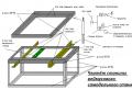
It is preferable to install gear pulleys for the motor and shafts, which will allow the use of a chain drive, which is characterized by a high degree of reliability. An asynchronous electric motor with a power of 4–5 kW is chosen as the engine. The schematic diagram of the arrangement of parts is shown in the figure:

1 – work table for feeding and dispensing workpieces; 2 – wood preparation; 3 – safety device; 4 – upper feed roller with a corrugated surface; 5 – front clamp; 6 – knife shaft; 7 – rear clamp; 8 – feed upper roller with a smooth surface; 9 – lower smooth shaft
The table base consists of rear and front parts, which are mounted on prepared adjustment devices. They are used to change the height of the table and the position of the workpiece being processed. Before starting work, be sure to check the location of the knives, the reliability of fastening and the correct sharpening.

Equipment setup
The setup is carried out as follows. The support rollers (8) are lowered below the level of the table (10), and the tabletop itself is lowered so that a pre-treated wooden block laid on it passes freely under the blade shaft. Slowly raise the table, simultaneously turning the shaft until it touches the surface of the block. At the moment of contact with the upper edge of the knife shaft, the position of the table is fixed.

Having lowered the working surface by 0.3 mm, the block is moved under the rear clamp (3), which is adjusted with screws (2), trying to get the template to touch. Additionally, it is lowered by 0.7 mm (total 1 mm from the initial level) and the measuring stamp is placed under the front clamp (5), the height of which is set with adjusting screws (6) until it touches the bar.
Having lowered the working surface another 0.5 (1.5 mm from the initial level), adjust the rear pressure shaft (1). Continuing to lower by 0.5 mm, use the measuring template to change the height of the grooved feed roller (7). Lowering it another millimeter, the measuring template is placed under the claw protection and the height is adjusted until it touches. Finally, the support rollers are placed above the table surface.
Processing a workpiece that is not pressed simultaneously by both shafts is prohibited!
Depending on the model of woodworking equipment, the adjustment dimensions may vary. When starting to process coniferous species, the difference in the height of the pressure rollers is set within 0.3 mm, for hardwood – 0.1 mm. When planing workpieces, it is important to observe safety precautions, so you should not:
- place your hands near moving and rotating mechanisms;
- clean during operation;
- repair live parts.
To prevent the possibility of electrical damage, the equipment must be grounded. Before turning on, be sure to check the serviceability of all mechanisms.
Woodworking tools from an electric planer
This is the option for making a thickness planer at home in many cases that is preferred by craftsmen who have an electric planer. The cost of modification while maintaining the principle of operation will be minimal, but the result is no worse than using expensive equipment. Instead of a table, a flat, powerful board is installed, on its sides there are width limiters on which the main unit is attached. The electric plane is mounted on a base with variable height.

The rear support metal plate on the planer is replaced with one made independently from OSB or large plywood. The thickness is chosen in such a way as to obtain the same level relative to the front plate, which regulates the gap for removing chips of 1-3 mm. The width of the work table and the base plate should be equal to each other.

At the side of the plate, screw the slats for fastening the legs of the required height. Since the standard width of knives is 8.2 cm, the thickness of the plane of the workpieces being processed, for example timber, should not exceed 10 cm, and the center-to-center distance for attaching the legs is 11–12 cm. Consequently, their length will be 14–16 cm, width above 3.5 cm , and the thickness is 1 cm. They are attached at the same distance from the edge of the plate.
A pre-assembled clamping device with an electric planer is installed on the working base, placing the attachment points strictly level. This is necessary for parallel movement relative to the working surface and guarantees the necessary processing accuracy with a homemade machine. If it is necessary to ensure pressure on the working tool, then use spring ties or a rubber band.
This is the most affordable option for manufacturing a thickness planer. Of course, such a tool can hardly be considered full-fledged, but the principle of operation and the final result make it suitable for performing simple operations at home.
What do you need to make a homemade jointer with your own hands? First you need to decide on the types of this tool.
There are three types of jointer.
- The first is manual, reminiscent of an elongated plane.
- The second is an electric planer, it looks like a circular saw with a horizontal knife.
- And the third is a jointing machine.
Its main parts are the statina and the jointing shaft.
How to make a jointer with your own hands?
The proposed version of the jointer will allow you to easily process workpieces longer than 60 cm. The basis of this woodworking machine is a Russian-made manual electric plane - Interskol.
The power tool has been slightly modified. For example, the original soles were removed. And additional holes are cut in the plastic body for easier release of chips from the plane.
To create a jointer, you will need a table to which an electric plane will be attached from below. The base of the machine table top is made of two corners soldered to each other. The total length of the working surface is 130 cm.
The photo shows the holes with which the plane will later be attached.
1) For precise and high-quality processing of wood, a stop is required. It must be welded perpendicular to the work surface. The same stop is welded on the other side.
2) Then the guide can be screwed to the welded stops. You can use flat boards as a guide. In our case, this is a piece of chipboard.

A very important point is that the serving and receiving parts of the table are at different levels. More precisely, the entire feeding part is 1 mm lower. This difference allows you to cut off a layer 1 mm thick from the workpiece. The feeding and receiving parts are connected to each other by two parts on the sides. The connecting parts in our case are a cut channel.
The table is assembled together using electrode welding. 2.5 mm electrodes were used so as not to burn through the metal. Welding was done by spot welding.
The machine stands on 3 legs. On one side there are two thin legs made of metal pipes, and on the other side there is a thicker leg. To answer the question why exactly 3 legs, you need to remember the geometry. After all, a plane can be drawn through any three points. A machine with three legs will stand firmly even on an uneven floor, while a four-legged machine will wobble in this case.

And in order to prevent the entire machine from falling apart, two metal pipes were welded along two diagonals. This increased the strength of the structure.
Once the table is assembled and ready, you can begin attaching the power tool. Standard mounting screws are used as connecting elements. They attached the original sole. The plane is attached from below. For a tighter fit, you can use a compensating gasket. The photo clearly shows that the gasket adds thickness.
By leaning the plane against the bottom and aligning the bolts with the holes, you can tighten the mounting bolts. They should be wrapped securely. So that the plane does not fall off later. Now you can turn on the assembled homemade jointer and feel free to work on it.
Video: homemade jointer.
Video: second part.
Video: third part.
Making a jointer with your own hands, if you have at least basic knowledge about the structure of this tool, is not at all difficult. The task is greatly simplified if you have an old electric planer in your arsenal - it will become the main component of a home planer.
The jointer is widely used in wood processing - with its help it is easy to make the surface smooth, get rid of unevenness and roughness, and give lumber a neat appearance. Having such a multifunctional tool at hand will significantly expand your woodworking capabilities. With a jointer it is easy to assemble furniture yourself, make lining or parquet.
Purpose of the jointer

Working with wood can be not only a pleasant hobby, but also an opportunity to provide all the necessary interior items. If you have specialized tools, homemade furniture will not differ much in quality and appearance from its factory-made counterparts. A jointer is one of these tools; it makes it possible to make the surface of wood perfectly smooth and prepare it for gluing, varnishing or applying a decorative design.
A jointer, or jointer, is a tool for finishing lumber of large lengths and widths. Processing is carried out by removing a small (1-2 mm) layer of material using a rotating shaft into which sharp blades made of hardened metal are mounted.
The principle of operation of a jointer is identical to the operation of a plane, with the difference that the jointer is fixed in place, and the material being processed moves. The extended length of the fixture allows it to be used to give a beautiful look to wide, flat surfaces
Selection of components for the jointer

In order to assemble a jointer from an electric planer, it is not at all necessary to disassemble a new tool. A plane that was previously used for its intended purpose is quite suitable. The disadvantage of some modern models of such devices is that their plastic casing becomes loose over time and cracks and chips appear on it. It becomes unsafe to work with such a plane, but it fully meets the requirements for creating a jointing machine. All you need to do is turn the plane over and secure it in this form in a pre-prepared workbench.
Choosing an electric planer model is one of the important points when assembling the machine. Most models have a planing width of 82 mm, which is quite suitable for home use. More expensive and powerful planes are equipped with a 100 or 110 mm shaft. In the latter case, such parameters make it possible to run boards and beams 10 cm wide through the tool, without leaving untreated areas.
It is worth paying attention to the additional functions of the electric planer: some models are already equipped from the factory with special devices that allow you to turn the tool into a full-fledged jointing machine. This type of planer can be fixed with the sole up, while safety is ensured by a spring-loaded protective cover.
If there is a need to process materials whose width exceeds 110 mm, then doing this with an electric planer will be very inconvenient, since the board will have to be run several times, which increases time and reduces the accuracy of the work. In this case, it is worth considering the possibility of assembling a powerful jointer, the main components of which will be a separate shaft and a powerful electric motor. Although the cost of the shaft is often more than half the price of all materials, having such a tool in your arsenal, you will no longer be limited in your woodworking capabilities.

The planing width of a full-fledged jointer equipped with a shaft ranges from 25 to 85 cm or more, but one must take into account the fact that an increase in this parameter entails an increase in engine energy consumption.
Optimal engine power depends on several parameters:
- shaft width;
- number of knives;
- width of processed lumber.
The relationship is direct: the greater the importance of the listed parameters, the higher the engine power should be. For home machines, 1.5-2 kW motors have proven themselves well. The shaft rotation speed of such machines is 4-4.5 thousand revolutions per minute, the width of the processed material is 25-40 cm.
Assembling a jointer
The jointer is assembled in several stages. First, you should assemble the body of the workbench, into which the electric planer will subsequently be mounted. The body looks like an ordinary wooden box without a bottom. It is covered on top with a thick sheet of plywood, in which a hole is cut for installing a plane. The plywood will bear the weight of the tool, and to work with the material it must be covered with two more sheets, the thickness of which will differ by 1-2 mm. They are installed on the right and left sides of the plane. Thin plywood plays the role of a serving table, and thick plywood acts as a receiving table.

The principle of interaction between the feeding and receiving tables is extremely simple: the lumber, moving along one half of the workbench, reaches the plane, and a layer of chips 1-2 mm thick is removed from it. The already processed wood ends up on the receiving part of the table, where it takes a stable position, thereby allowing the rest of the board to pass over the plane. In addition to the support function, this reduces vibration and makes it possible to provide reliable support during work.
Assembling a jointing machine with a shaft is a little more difficult, but if you have experience, it will not take much time either. Such a machine consists of similar parts - a housing, a feeding and receiving table, and a compartment for collecting chips. In such a model of a home-made device, a speed reducer will not be out of place, which will allow you to reduce the speed of rotation of the shaft to pass problem areas - significant irregularities, knots, etc. Of great importance is the calculation and precise adjustment of all housing elements to each other, ensuring reliable engine mounting and ideal alignment of the work tables.
Safety precautions when working
The jointer, due to the combination of dangerous factors - high shaft rotation speed and the presence of sharp blades, is a potentially traumatic equipment. Working with it requires strict adherence to a number of safety rules. This is especially true for homemade instruments: incorrect calculation of the elements that make them up often leads to fatal consequences. To avoid problems when working with a jointing machine, you need to adhere to the following requirements:

- Before starting work, you need to wait until the shaft reaches maximum speed.
- Under no circumstances should the working tool be inspected, lubricated or cleaned of chips during operation. To do this, you need to stop the machine, turn off the power and only then start servicing.
- When processing small parts, the length of which does not exceed 40 cm and the width - 5 cm, you should use a special vertical stop. It looks like a thick board, which is fixedly attached to the feeding work table.
- To increase operational safety, the jointer shaft can be equipped with a special protective flap. As the material moves forward, it moves away, and after processing is completed, it returns to its original position using a spring system. The blades of the shaft remain closed from accidental contact.
- Lighting is of great importance - all work should be carried out under the light of a powerful lamp, or outside.
13.02.2017
Administrator Chief
Design of jointing machines
On single-sided jointing machines, one of the planes of the workpiece (usually the face) is aligned or sequentially, in two transitions, two planes of the workpiece. The working body is a horizontal knife shaft, on which two, less often four, legs are installed. The machines are designed for processing workpieces and panels up to 600 mm wide.
The diagram of a single-sided jointing machine is shown in Fig. 130 The machine bed is cast, box-type. The machine has front and back tables, a guide ruler. The guide ruler is cast, with well-processed supporting and vertical planes. It is mounted on the machine using a bracket.
The knife shaft is mounted horizontally on the frame in ball bearings. The shaft is covered with a fan guard, hinged on the machine. Thanks to the spiral spring, the guard is pressed against the guide fence, completely covering the cutter shaft.
Each table is mounted on two eccentric rollers, movably mounted in separate slides for each table. The slides are attached to the frame with bolts. Eccentric rollers allow you to move the tables in height, and the slides allow you to move the tables closer or further away from the knife shaft.

Rice. 1. Schematic diagram of a single-sided jointing machine: 1 - rear table, 2, 15 - eccentric rollers, 3 - thrust. 4 - bracket, 6 - nut, 6 - blade shaft, 7 - fan guard, 8 - bracket for fastening the guide bar, 9, 11 - screws, 10 - rod, 12 - guide bar, 13 - front table, 14 - mechanism handle lifting and lowering the front table, 16 - slide, 17 - installation location of the push-button station, 18 - hand brake levers, 19 - blade shaft lock, 20 - bed, 21 - electric motor, 22 - hand brake housing
The horizontal position of the tables when lifting and lowering is maintained thanks to the pairwise connection of eccentric rollers in rods-screws 3. The front table is lowered and raised by moving the handle in the plane of the sector with divisions; The height position of the rear table is adjusted by changing the position of the screw rod with nuts.
The starting equipment of the electric drive is built into the frame. A special device can be provided for sharpening and jointing knives directly on the knife shaft.
Double-sided jointing machines have a second working body - a vertical spindle, which allows them to simultaneously process two surfaces of workpieces (face and edge) with the formation of a right angle between them.
In addition, they differ from single-sided jointing machines by the presence of a composite guide ruler. The machines are equipped with automatic feeders, depending on the design of which, height changes are adjusted using a handwheel.

Rice. 2. Double-sided jointing machine S2F4-1: 1 - bed, 2 - rear table, 3 - handwheel for the mechanism for raising and lowering the car lift, 4 - automatic feeder, 5 - guide ruler, 6 - front table, 7 - handle for the table height adjustment mechanism, 8 - control panel

Rice. 3. Diagram of a vertical spindle and a composite guide ruler of a double-sided jointing machine: 1 - fixed part of the ruler, 2 - fixing screw, 3 - bracket, 4 - stand, 5 - V-belt drive, 6 - electric motor, 7 - screw for belt tension, 8 - plate for securing the electric motor, 9 - handle for installing the bracket, 10 - eccentric for installing the movable part of the ruler, 11 - movable part of the ruler, 12 - cutter head, 13 - spindle When changing the cutting tool, the automatic feeder is moved to the side. To brake the knife shaft, an electromechanical brake is provided, interlocked with the “Stop” button of the machine. The spindle (Fig. 3) is secured with a bracket on a fixed stand. The electric motor is connected to the spindle through a V-belt drive. The spindle rotates at a frequency of up to 7000 rpm, the cutting circle diameter is 104 mm. There is a cutter head on the spindle. The guide ruler is composite: its main part is stationary, the moving part is moved in a horizontal plane by turning the eccentric. When the eccentric is fully rotated, the moving part of the ruler moves relative to the fixed part by 2 mm. Selecting an operating mode First of all, it is necessary to determine the thickness of the wood layer to be removed, and if the machine is equipped with an automatic feeder, then the feed speed. The thickness of the removed layer depends on the warpage of the workpieces, the magnitude of which is determined by trial processing of 3-5 workpieces. If the processed workpieces have unplaned areas, the front table is lowered to the required amount. If the warp value is more than 2-3 mm, jointing is carried out in two passes.

Rice. 14. Surface processed by milling method: a - general view, b - surface with the trajectory of movement of the cutting edge of the cutter Knowing the feed rate per knife, cutting radius, number of knives and rotation speed of the knife shaft, it is possible to calculate the numerical value of the size of irregularities and thus the roughness class processing and, conversely, determine the permissible feed rate based on a given surface roughness class. Setting up the machines Setting up single-sided jointing machines involves setting the rear and front tables in height, as well as the guide ruler. The working surface of the back table must coincide with the horizontal tangent to the cylindrical cutting surface or be 0.02-0.03 mm below it. In this position, kinematic irregularities do not rest against the table sponge. To set the table in the required position, take a properly processed block of hardwood, place it firmly on the table and manually turn the cutter shaft. If the knives lightly touch the block, then the table is installed correctly, the block lies on the knife - the table must be raised. Raise the table by moving the nut with a wrench along the screw-rod connecting the eccentric rollers of the rear table. The back table is adjusted after each change of knives and their sharpening and jointing directly on the shaft. The position of the front table relative to the back one depends on the thickness of the layer of wood being removed, which should not exceed 2 mm. It is determined by the distance from the working plane of the front table to the horizontal tangent to the cylindrical cutting circle. The table is moved in height using a handle, positioning it against the corresponding division marked on the sector. The design of the table movement mechanism allows you to quickly raise and lower the table by moving the handle, which is used for longitudinal milling of warped workpieces. Having adjusted the tables in height, check the distance between the table jaws and the cutting edges of the knives. It should be within 2-3 mm. It is measured with a calibrated plate of appropriate thickness. The plate should fit easily, but without play, into the gap between the sponge and the knife blade. If the distance is more than 3 mm, tears appear on the workpiece; less than 2 mm, the cutting edge of the knife is chipped. Adjust the gap size by turning the shaft until the knife is against the jaw. By unscrewing the screws, move the slide with eccentric rollers until a gap of 2-3 mm is obtained along the entire length of the knife shaft. After this, the slide is securely fastened. When jointing block workpieces, the distance between the guide ruler and the left end of the knife shaft should be slightly larger than the width of the workpiece being processed. As the knives become dull, the ruler is gradually moved to the right to ensure that the undull areas of the knives are involved in the work. The guide ruler is moved across the table by a rack and pinion mechanism driven by a handwheel. To longitudinally mill the edge of a part at an angle to the face (usually 90°), a guide ruler is installed using a metal square or (at an angle other than a straight line) an appropriate template. To do this, a control square (template) is installed on the rear table of the machine. The gap between the flange of the template square and the surface of the guide ruler should not exceed 0.05 mm over a length of 1001 mm. The guide ruler, installed at a certain angle, is fixed with a screw. When setting up double-sided jointers, the tables and the stationary part of the guide fence (above the back table) are set up in the same way as in single-sided jointers. The plane of the moving part of the guide ruler (above the front table) should be separated from the plane of the fixed part of the guide ruler by the thickness of the layer of wood removed from the edge of the workpiece. It is installed in the desired position by turning the eccentric handle, which moves along the hob, which has the shape of a semicircle. If the handle is in the middle of a semicircle, will the ruler take a position at which the thickness of the cut layer of wood will be equal to 1 mm? if the handle is located at 1/4 of the semicircle - 0.5 mm, etc. The tangent to the cylindrical cutting surface of the knives of the head mounted on a vertical spindle must coincide with the plane of the stationary part of the guide ruler or be 0.01-0 away from it .02 mm. To install the head, a block with aligned planes is pressed against the stationary part of the ruler and the bracket carrying the head is rotated until the cutter head takes a position in which the cutting edges of the knives lightly touch the block. In this position, the head is fixed by tightening the bracket locking screw. Both automatic feeders and conveyor feeders are configured to feed workpieces of a certain thickness. Workpieces must be fed without “slipping” and with slight pressure on them from spring-loaded rollers, chains or claws. The supply of workpieces also depends on the location of the automatic feeders. When processing sheets, it is better to install the automatic feeder behind the knife shaft (at a distance of 30-40 mm from it); when processing thick workpieces, the feeders can be located above the front table. The automatic feeder is installed at a slight angle to the guide ruler, which ensures that the workpiece being processed is pressed against it. Automatic feeders are also used on single-sided jointing machines. To joint the edges of the workpieces, they are installed parallel to the guide line; in this position, the automatic feeder elements press the workpiece against the guide line and the machine table. The setting is checked by test jointing. Deviation from plane should not exceed 0.15 mm over a length of 1000 mm and from perpendicularity - 0.1 mm over a length of 100 mm. Working on machines One worker works on a single-sided jointing machine, two workers work on a double-sided jointing machine. The machine operator takes the workpiece from the stack, inspects it and places it with the concave surface down on the front table. Pressing the workpiece against the guide ruler with both hands, he feeds it to the knives. Subsequently, when moving the workpiece with his left hand, he presses the processed part of the workpiece to the plane of the back table. After the next pass, the machine operator again inspects the workpiece and either puts it in a stack, or, in the case of a simple horn, sends it back to the machine. Workpieces with a heavily warped surface should not be planed, since the chips have to be removed in several passes and the thickness of the workpieces as a result of such processing is reduced to the size at which they are scrapped. 
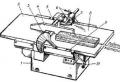
Rice. 5. A device for feeding short workpieces to the cutting tool: 1 - workpiece, 2 - pusher. If you need to align two mutually perpendicular surfaces of a part, first align the wider one (for example, a face), and then press the workpiece with this surface to the guide ruler and mill it second surface (edge). On a double-sided jointer, this operation is performed in one pass. You cannot mill to size in thickness or produce workpieces with parallel planes on a jointing machine. This is done on other machines, for example surface planers. The optimal length of parts processed on jointing machines is 1-1.5 m; shorter workpieces should be milled using a special device (Fig. 5); Planing longer ones is inconvenient and difficult due to the large mass. If the treated surface has curvature or wingedness, it is necessary to verify the position of the tables relative to the knife shaft. When “beating” the workpiece with knives, mossiness and arson appear on the treated surface, the knives should be sharpened; If two adjacent planes are not at right angles, you need to adjust the guide ruler. When fed manually, workpieces shorter than 400 mm, 50 mm and thinner than 30 mm can be guided to the cutting tool only by pushers, and curved workpieces - by templates. It is prohibited to perform shaped longitudinal milling and quarter cutting on jointing machines. - Design of jointing machines. Planing machines are distinguished by the largest width of the workpiece being processed: 250 mm (SFZ-Z, SFAZ-1, S2FZ-E), 400 mm (SF4-1, SF4, S2F4-1) and 630 mm (SF6-1, SF6). Depending on the number of cutting mechanisms, there are single- and double-sided machines. On double-sided machines (S2FZ-E, S2F4-1), two surfaces of the workpiece are milled simultaneously: the face and the edge. Based on the type of feeding of the processed material, a distinction is made between jointing machines with manual and mechanized feed. Mechanized feeding is carried out by attached automatic feeders (SFAZ-1, SFA4-1) or a conveyor feed mechanism built into the machine (SFK6-1). To collect and remove chips and dust, the machines are equipped with chip receivers connected to the factory exhaust network. The single-spindle jointing machine SF6 is shown in Fig. 1. The cutter shaft, front and rear tables and guide ruler are mounted on the box-shaped frame. The knife shaft is mounted on ball bearings and is driven by an electric motor through a V-belt drive. The electric motor is located on the sub-motor plate inside the frame. To quickly stop the knife shaft there is a brake operating from an electromagnet.

Rice. 1. Single-spindle jointing machine SF6: 1 - bed, 2.8 - tables, 3 - guard, 4 - guide ruler, 5 - knife shaft, 6 - clamps, guide ruler fastenings, 7 - bracket, 9 - scale, 10 - handle table height settings To change the thickness of the layer being removed, the front table can be moved in height relative to the knife shaft. The back table is designed for precise positioning of the machined surface of the part. It is made unregulated, i.e. rigidly attached to the frame, or adjustable in height. Having an adjustment mechanism makes it easier to set up the machine. The guide ruler is designed for precise lateral alignment of the workpiece. It is made in the form of a narrow plate and mounted on a bracket. It can be tilted towards the working surface of the table and moved across the width of the machine. The working area of the knife shaft is closed by a fan guard. The double-sided jointing machine with horizontal and vertical spindles S2FZ-2 is designed for simultaneous milling of the face and edge of the workpiece. Unlike a single-sided jointing machine, it is additionally equipped with a vertical edge jointing head, front and rear guide rulers. The front ruler can be adjusted relative to the head to the thickness of the layer being removed. The edge jointing head is driven into rotation by an individual electric motor mounted on a bracket at the back of the bed. The processed material is fed by rotating rollers of the automatic feeder. The jointing machine with a built-in conveyor SFK6-1 has a conveyor feed mechanism. It is made in the form of an endless chain put on sprockets, one of which is drive. Spring-loaded, pointed metal claws are attached to the chain links for a secure grip on the workpiece. The feed mechanism is mounted on two stands and can be moved in height by a separate electric motor through screw and worm gears. Setting up machines. Setup includes installing knives in the knife shaft, adjusting the position of the tables, guide ruler and feed mechanism. Properly prepared knives should be installed in the knife shaft. They must be sharpened, balanced and balanced. Before installing knives into the knife shaft, you must: turn off the input switch; turn the automatic feeder to the non-working position or raise the support of the conveyor feed mechanism; move the guide ruler to the extreme right position; lower the front table to its extreme position; secure the blade shaft with a locking device; loosen the screws securing the knives and remove dull knives; clean the grooves in the body and wedges from chips, dust and resin; install the prepared knives. The knife is installed in the knife shaft so that its cutting edge protrudes beyond the edge of the pressure wedge (chip breaker) by 1.5...2 mm when the thickness of the cut layer (chips) is more than 0.2 mm and 0.5...1 mm when the thickness of the chips is less 0.2 mm. The non-parallelism of the cutting edge of the installed knife on the working surface of the rear table should be no more than 0.1 mm over a length of 1000 mm. To achieve the required installation accuracy, control and installation devices are used (Fig. 2). The accuracy of installation is controlled with a ruler or a wooden block with a section of 30 X 50 mm and a length of 400 mm. The block is placed on the rear table of the machine at the end of the knife shaft (Fig. 2, a). The shaft is rotated manually and, having loosened the fastening screws, the position of the knife is changed so that the cutting edge touches the block. The fastening screw closest to the block is lightly tightened. When relocating the block, check the position of the other end of the knife. Adjust the position of the knife so that its edge along its entire length is positioned equally relative to the block. The following knives are adjusted in the same way. The adjusted knives are finally secured with screws. A gap between the knives and the housing jaws is not allowed. The quality of installation of knives is controlled by the force of turning the knife shaft manually and by the sound that occurs when the knife comes into contact with the working surface of the template. In some cases, to achieve installation accuracy, a template made in the form of a C-shaped bracket is used (Fig. 79.6). The bracket is equipped with base supports with which it is installed on the knife shaft housing. The template is pre-configured. Using the screw, adjust the base stop to ensure optimal protrusion of the knife relative to the body. When setting up, bring the cutting edge of each knife until it touches the base stop. By moving the bracket along the knife shaft, ensure that the knives are parallel to the shaft body. The device with an indicator (Fig. 2, c) has a body with precisely ground plates, in which a dial-type indicator is fixed. The device is installed on the back table so that the stop touches the cutting edge of the knife. The position of the knife in the body is adjusted using the indicator scale. The device allows you to achieve the installation of knives on the same cutting circle with an error of up to 0.02 mm while ensuring parallelism and the necessary release of the knives relative to the working surface of the rear table. After final tightening of the spacer bolts, the knives may move. Therefore, you should once again check that they are installed correctly, rotate the shaft idle and make sure that the knives are securely fastened. The back table is installed so that its working surface is tangent to the circle described by the cutting edges of the knives, or 0.02...0.03 mm below it (Fig. 3, a). If a verified template (control ruler) is used when setting up the knife shaft, then the knives will be installed tangentially. If a control and adjustment device is used during adjustment, basing it on the cylindrical surface of the knife shaft housing, it is necessary to adjust the position of the rear table in height. The table is adjusted by turning the eccentric rollers through rod-screws 2 with a nut 3, and the accuracy of the installation is controlled by a verified template or an indicator device.

Rice. 2. Alignment of knives in the knife shaft of a jointing machine: a - with a control ruler or a wooden block, b - a template, c - a device with an indicator; 1 - block, 2 - table, 3 - knife shaft, 4 - stop, 5 - bracket, 6 - lock nut, 7 - screw, 8 - body, 9 - indicator When processing block parts, the guide ruler is positioned so that the distance to the left end the knife shaft was slightly larger than the width of the workpiece being processed. As the knives become dull, the ruler is moved to the right and the parts are processed with that part of the knife shaft on which the knives have not yet become dull. When processing parts with non-perpendicular adjacent surfaces, the guide ruler is positioned so that the angle between its working surface and the knife shaft is obtuse. The fence guides on a double-sided jointer perform the same functions as the front and back tables. The rulers are adjusted relative to the edge jointing head using a handle, and the amount of the layer to be removed is set using a scale mounted on the frame. The automatic feeder or conveyor feed mechanism is adjusted in height (Fig. 3, b) using a handwheel, depending on the thickness of the workpieces being processed. The distance from the working surface of the front table to the feed rollers (conveyor fingers) should be 2...3 mm less than the thickness of the workpiece. The automatic feeder is positioned above the knife shaft so that the first feed roller is above the front table at a distance of 50...60 mm from the knife shaft, and the other rollers are above the rear table. The automatic feeder is oriented relative to the guide ruler so that the rollers are not parallel to the axis of the knife shaft (angle 1...30), for which the automatic feeder is rotated relative to the vertical axis. This arrangement of the feed rollers allows the workpiece to be pressed against the guide ruler and improves the conditions for its basing. The pressure of the feed elements on the workpiece must be sufficient to feed without slipping. Excessive pressure causes increased wear of the automatic feeder mechanisms and deformation of the part in the cutter shaft area.

Rice. 3. Setting up a jointing machine: a - setting up tables, b - installing an automatic feeder; 1 - rear table, 2 - rod-screws, 3 - nut, 4 - knife shaft, 5 - front table, 6 - handle for adjusting the thickness of the layer being removed, 7 - scale, 8 - eccentric roller, 9 - rods The front table is installed like this, so that its working surface is below the upper generatrix of the circle described by the cutting edges of the knives. The amount of protrusion of the knives relative to the front table determines the thickness of the layer to be removed. Since the thickness of the largest layer depends on the degree of warping of the workpiece, the table height is adjusted before processing each workpiece. By rotating the eccentric rollers through the rods, handle 6 raises or lowers the table. The amount of lift is controlled on a scale. Work on jointing machines (jointers). When processing small workpieces, a manually fed planer is operated by one worker. The machine operator takes a workpiece from the stack, visually evaluates the convex and concave edges of the workpiece and places it with its concave surface on the front table. Severely warped and defective workpieces should be rejected. Pressing the workpiece against the table and the guide ruler from the side with the left hand, feed it onto the knife shaft with the right hand. When moving, the front end of the workpiece moves the fan guard and thus provides access to the rotating knives. After processing the front end of the workpiece, you should firmly press the processed part to the plane of the back table with your left hand and continue feeding. When feeding, carefully monitor the position of your hands relative to the knife shaft and keep them at a safe distance. When processing small parts, there is an increased risk of injury, so workpieces shorter than 400, narrower than 50 and thinner than 30 mm are fed into the machine only with a special pusher (Fig. 81). After each pass, the machine operator evaluates the quality of the processing and, if the surface is not planed, re-planes it. If two surfaces of a part need to be aligned, then first the face is milled, and then the edge, pressing the part with the previously processed surface against the guide ruler. On double-sided machines, these operations are performed in one pass. When processing massive and large-sized parts, the machine is operated by two workers. The machine operator positions and feeds the workpiece, and the second worker, standing behind the machine, helps at the final stage of processing, receives the finished part and places it in a stack. If necessary, additional roller tables are installed in front and behind the machine. The manual feed speed on the machine is selected individually for each workpiece, depending on the defects and the required milling depth. When counter-cutting and milling against the grain, the speed should be reduced. The milling depth depends on the processing allowance and the size of the defects.

Rice. 4. Scheme of processing small parts using a pusher
Removing stock in one pass usually does not allow obtaining the required quality of processing. The best effect is achieved in two or more passes at a small milling depth, since in this case the deformation of the part under the influence of clamping forces and internal stresses in the workpiece material is reduced.
In machines with mechanized feed, the feed speed is selected according to a schedule based on the condition of maximum load of the cutting motor and ensuring the specified surface roughness.
The resulting parts must be checked for accuracy of processing. By applying the treated surfaces one part to another, the size of the processing error is visually judged by the size of the gap between them. In addition, the flatness of the machined surface can be checked with a straight edge and feeler gauge. The deviation from the plane should not exceed 0.15 mm over a length of 1000 mm. Adjacent treated surfaces must be mutually perpendicular. The permissible deviation is 0.1 mm at a height of 100 mm. Perpendicularity is checked with a test square and feeler gauge. The roughness of the treated surface should be 60... 100 microns. If the parts do not meet the specified requirements, the machine should be adjusted.
Video of the operation of a used SF4-1 jointing machine after repair at NEVASTANKOMASH LLC
Video of the operation of a used S2F4-1 jointing machine after repair at NEVASTANKOMASH LLC
Video of the operation of a used SF4 jointing machine with an automatic feeder after repair at NEVASTANKOMASH LLC
On our website www.site we have repeatedly published materials about woodworking “circular” machines with a circular saw and a jointer, which are so necessary for home craftsmen.
Based on these publications, I made a similar machine for myself. But when I did it, I realized that not everything about it suits me. In particular, the mechanism for raising and lowering the table. And it was only a stretch to call this device a mechanism.
Work progress on the manufacture of a woodworking machine
The table was mounted on four stud posts, and to move it vertically it was necessary to unscrew and tighten as many as eight nuts. Moreover, it was necessary to set the table plane parallel to the axis of the plane (and circular saw) “by eye.” In the end, I decided to make another table, with a more “advanced” mechanism for raising and lowering it (the table).The base of the lifting table is the frame. Its dimensions are consistent with the dimensions of the top of the circular frame.
The frame is made of steel equal-flange angle No. 6.3 and is collapsible: its transverse elements (I have them 425 mm long) are attached to the longitudinal ones (their length is 560 mm) with Mb screws. But it couldn't be done without welding. At the ends of the longitudinal elements, end plates are welded, cut from 5 mm steel and sawn along the internal profile of the corner. The plates have three holes with a diameter of 6.2 mm, and the vertical shelves of the crossbars have corresponding MB threaded holes through which the elements are fastened with MB screws. In the longitudinal elements, at a distance of 60 mm from the ends and 15 mm from the upper edge of the vertical shelf, two holes with a diameter of 18 mm were drilled for the shaft support bushings.
The support bushings are machined from sections of half-inch water pipe, inserted into the holes and welded to the corners. But it is better to do this simultaneously with the installation of the shafts - then it is easier to maintain the alignment of the bushings and ensure ease of rotation of the shafts in them, for which it would be useful to apply grease to the rubbing surfaces.
The shafts (there are two of them) are solid steel rods 430 mm long, machined from a cylindrical rod with a diameter of 18 mm. One of the ends of each shaft is turned into a square with a side of 12 mm - a lever is put on it, with the help of which the table is raised and lowered.
The lever is a handle welded to a cylindrical hub with a central (axial) square hole corresponding to the square at the end of the shaft.
There are also two levers, like shafts. To ensure uniform lifting of the table, the levers are connected to each other by a rod made of a steel strip with a cross-section of 3x20 mm. The rod is mounted freely on axles welded to the levers.
The main elements that raise and lower the table are eccentrics. They are machined from a steel round rod with a diameter of 46 mm. The holes in each of them with an eccentricity of 5 mm were also drilled on a lathe. To do this, when clamping the part in the chuck, a steel plate 10 mm thick was placed under one of the jaws. The table travel (its vertical movement) after this was also 10 mm.
The eccentrics are mounted on the shaft and secured to it by welding. Before welding, you must make sure that all eccentrics are directed in the same direction with the same position of the levers.
But before that, bushings with brackets welded to them for fastening the table are put on the eccentrics. In the photo, for clarity of the entire structure, the table is made of plexiglass and attached to the cradle with screws with large (not countersunk) heads. In reality, the table itself is large in size and its edges extend beyond the frame (but only such a sheet of plexiglass was available).
The lifting table frame is mounted on the top members of the machine frame, and both structures are bolted together through corresponding holes drilled at the same time.