The building where the reverse osmosis plant is located. What is the TDS value in tap water? Comparison of reverse osmosis filters.
REVERSE OSMOSIS. THEORY AND PRACTICE OF APPLICATION.
(
1. WHAT IS "OSMOSIS AND REVERSE OSMOSIS"?
The phenomenon of osmosis underlies the metabolic process of any living organism: nutrients enter each living cell, and metabolites are excreted back. All these processes are carried out through the so-called semi-permeable membranes, which are able to pass the molecules of some substances and prevent the passage of molecules of other substances through them.
The essence of the phenomenon osmosis is that if there are aqueous solutions of salts with different concentrations on opposite sides of a semipermeable membrane that can pass only water molecules, water molecules will move through the membrane from a weakly concentrated solution to a more concentrated one. Moreover, if both solutions are under external, equal pressure (for example, atmospheric), then due to the phenomenon of osmosis, i.e. as a result of the process of water penetration through the membrane, an increase in the liquid level in a more concentrated solution is observed. This difference in the height of the levels of two solutions of different concentrations is proportional to the force under which water passes through the membrane. This power is called osmotic pressure».
If, on the other hand, a solution with a higher concentration begins to be affected by an external pressure that exceeds the osmotic pressure, then water molecules will begin to move through a semipermeable membrane in the opposite direction, that is, from a more concentrated solution to a less concentrated one. This process is called " reverse osmosis". If, however, an external pressure equal to infinity is applied, then, purely theoretically, it is possible to “transfer almost all the water” from a more concentrated solution, and, thus, divide the initial solution into “pure and dirty water».
From the point of view of technological processes of water purification, reverse osmosis refers to membrane mass transfer processes with a transverse current, in which the source water flow is divided into two streams - "clean" water - permeate and "dirty" water - concentrate. In this case, the ratio of the amount of obtained permeate (purified water) and the amount of initial water, expressed as a percentage ( English recovery of a reverse osmosis), are called: degree of extraction of permeate (purified water) or permeate output (purified water).
In addition, such cartridges generate waste. Some manufacturers take used cartridges for recycling. This is a specific sector that is implemented by the manufacturer, there is no “public” channel through container parks. Drink tap water daily if you don't like the taste of the water you have at home; Make coffee or tea. Given the variable potency and release of other compounds such as silver, it is difficult to recommend the use of decanters. The filter must be changed regularly.
Reverse osmosis and ceramic filter: two systems for rainwater
There are also filters that are installed directly at the outlet of the tap. These filters work on the same principle as filter jugs. They seem to be more effective than decanters for reducing nitrates. For filter reverse osmosis the whole set of equipment under the sink is required. It consists of a membrane pierced with holes so fine that they only allow water to pass through and not the rest. Filters out microorganisms, organic molecules and most minerals. These filters eliminate problematic ingredients, but also useful minerals.
2. HISTORY OF THE DISCOVERY AND DEVELOPMENT OF THE PHENOMENON OF OSMOSIS
From what has been said above, it is clear why the origins of the science of membranes are not physicists and chemists, but botanists and physiologists. Man did not invent semi-permeable membranes, he took a ready-made idea from living nature. Indeed, the main studies carried out at the end of the 18th - beginning of the 19th centuries were aimed only at describing and understanding the mechanism of processes occurring in living organisms, and only at the beginning of the 20th century did timid attempts to model the properties of biological membranes from artificial materials begin to appear.  The honor of discovering the phenomenon of osmosis is attributed to the French abbe Jean-Antoine Nolet, who in 1748 first noticed and described this phenomenon. Historians associate a certain incident with this discovery: once the abbe Nole poured the wine he had not drunk into a pig bladder and immersed it in a barrel of water. The next morning, taking the bubble out of the barrel, he noticed that the bubble was swollen. After tasting the wine, the abbot realized that it had become diluted. The abbot concluded that the wine became diluted due to the fact that water penetrated into it through the wall Bladder under the influence of a certain force, which arose due to the difference in the water content in the barrel and in the wine. At the same time, the abbot noticed that only water penetrated through the wall of the bubble. The abbot called this unidirectional force osmotic pressure, and the process itself - osmosis. (from the Greek ὄσμος, which means push, pressure). Thus, for the first time in the world, Abbé Nolet was able to describe the phenomenon of osmosis and the basic properties of a semipermeable membrane, and osmosis was forgotten. And only a century later another Frenchman - botanist and naturalist Henri Dutrochet
  a deeper study of this phenomenon was continued, which in turn described the processes of absorption of water and substances dissolved in it by plants by the laws of osmosis.
In the middle of the 19th century, the osmotic permeability of the cell membranes of the century was also studied by the physiologist Mol and the botanist Negeli. And since the end of the XIX century. physical chemists joined them, one of whom was the German scientist Adolf Fick, who in 1855, while studying the transfer through artificial membranes made of nitrocellulose, formulated the phenomenological laws of diffusion, later named after him. Graham first introduced the concept of "osmotic force" in 1854.
Fundamental studies of the osmotic permeability of cell membranes, made in 1860-1875 by the Dutch botanist and geneticist Hugo de Vries, one of the scientists who rediscovered Mendel's laws, together with the results of the work of W. Pfeffer (1877), formed an important part of the evidence, on the basis of which Ya. H. Van't Hoff built his theory of chemical equilibrium in dilute solutions (1886), and the Swedish scientist Arrhenius built his theory of electrolytic dissociation. In 1888, the German physical chemist Nernst derived an equation for the diffusion potential, and in 1911 Donnan formulated the laws of membrane equilibrium.
On this path of development, biology and membrane research diverge: the study of cellular, biological and membranes of natural origin remains with biology, while chemists and physicists who study membranes shift their interests towards the creation of membranes of various nature and the study of their properties, as well as the description of mass transfer processes Through them. So in late XIX early 20th century membrane separation methods were discovered: electrodialysis (Maigrot and Sabatier); gas separation (Graham), ultrafiltration (Bechgold). And in the early 1930s, the first mention of the reverse osmosis retention of electrolytes by membranes during the filtration of solutions appeared (Ershler, McBain).  By the end of the 20s of the XX century. significant material on the preparation and use of selectively permeable membranes was accumulated and generalized. The 1930s are characterized by research in this area by Alford, Ferry, Manegold, Grabar, the 1940s and 1950s by the improvement of methods for forming membranes for ultrafiltration and the production of ion-exchange membranes.
In the late 1950s and early 1960s, as a result of the work performed first by Reid, and then by Loeb and Suranjan, the design of a spiral OO module based on an anisotropic semi-permeable membrane was developed, which is able to withstand enormous pressure and has a high throughput with minimum dimensions. With the participation of Loeb in 1967, a desalination plant with a capacity of 150 m 3 per day was built in the town of Yotvata, which produced clean drinking water from an underground lake with a salinity ten times higher than that of the sea. These scientists showed the technical feasibility of using such membranes for desalination of sea and brackish waters, as well as the separation of liquid mixtures, which gave impetus to further study of membrane separation processes and the production of membranes with desired properties. We will discuss this further in the section on OO membranes.
Reducing the mineral content of food water can affect health. This can cause or exacerbate deficiencies, especially in people whose diets are deficient or balanced. These systems are mainly used to prepare rainwater at the end of filtration.
The ceramic filter is a filter with very fine holes. If the principle is different, the result is similar to the previous one. This filter is used for pre-filtration of drinking water. All filtration systems require maintenance. The manufacturer's instructions must be strictly observed. Poorly maintained filters can stop functioning properly or even pollute the water.
3. Models for the transfer of water and salts through an OO membrane
Although reverse osmosis technology has become a fairly common method of water treatment, the mechanism for transporting salt and water through the membrane remains a constant subject of debate. At one time, several models of water and salt transport through the OO membrane were proposed, the general provisions of which will be briefly considered below.
The simplest and easiest to understand model of an OO process is the “sieve” model, or molecular sieve separation model. This model assumes that salt and water are separated on the membrane due to the difference in physical size between the water and salt molecules and the pore size of the membrane. Most of the inhabitants prefer this particular concept of reverse osmosis water purification mechanism. However, it should be noted that in systems where the salt is mainly sodium chloride ( salt) the sizes of salt molecules (i.e. sodium ion and chloride ion) and water are almost the same. Therefore, this fact makes it possible to exclude the model of the "sieve" mechanism of water separation.
Another model of the transfer mechanism is diffusion transport model(still shared by some researchers), according to which both water and solutes penetrate the membrane by diffusion. According to this concept, water is fixed on the membrane surface due to hydrogen bonds, and this film prevents salts from entering the membrane pores. Water diffuses from one side of the membrane to the other, forming the same barrier layer there. This implies that the rate of diffusion transfer of water is greater than that of dissolved substances.
Finally, the third concept of ion transport through the OO membrane is capillary - filtration model selective permeability. According to this model, a layer of bound water is formed on the surface and inside the pores of a hydrophilic membrane placed in an aqueous solution. Water can bind to the membrane material, for example, by forming hydrogen bonds with the hydroxyl or carboxyl groups of the surface layer of the membrane. Bound water, having a network of directed intermolecular hydrogen bonds, completely fills the pores of reverse osmosis membranes and differs significantly from free water in its properties. For molecules and ions of dissolved substances, this water is a special phase into which they penetrate with a certain distribution coefficient, which can be much less than unity.
The degree of penetration of ions into the layer of bound water depends on the hydrophilicity of the membrane and the hydrating ability of the ions.
The polishing barrier increases the health of water intended for human consumption, and distillation and reverse osmosis are two ideal polishing barriers that are very effective in removing impurities that were not stored by the barriers. pre-treatment, One of the contents of this section is available later.
The distillation apparatus heats the water to turn it into steam, which is then cooled to purify the purified water. During the process, harmful microorganisms are destroyed. Dissolved minerals precipitate in the form of tartar. Some distillation apparatuses, with the help of additional treatments, remove organic chemicals capable of recondensing. The mineral content of distilled water is very low; Which, according to some, is a nutritional disadvantage.
4. REVERSE OSMOSIS MEMBRANES
We have already mentioned that the foundations for obtaining artificial film membranes were laid by Fick in the middle of the 19th century, and at the beginning of the 20th century, Bechgold studied the laws governing the formation of membranes with desired properties. In 1927, the German company Sartorius received the first samples of artificial membranes. After the Second World War, the Americans, using German developments, set up the production of cellulose acetate and nitrocellulose membranes. The effect of electrolyte retention by these membranes during the filtration of solutions through them was first described by Ershler and McBen, and 20 years later was studied in detail by Schmid and Schwartz, which coincided in time with the first studies of reverse osmosis on cellulose acetate membranes (Reid, Breton). At the same time, the theoretical foundations of this phenomenon were formulated for the first time.
However, the results of these works were of no interest for technology due to the very low productivity of the membranes, which was due to their relatively large thickness (> 100 µm). The reverse osmosis process gained practical significance only after asymmetric membranes were developed. The history of the development of membranes for reverse osmosis is described in detail by Suranjan in the 70s of the last century in his works on reverse osmosis: “ Reverseosmosis" and "Reverse osmosis and synthetic membranes".
Distillation apparatus components. Flying gas box Boiler room Cooling coil Steam cooling fan Carbon filter Heating element Distilled water faucet Water relief valve Distilled water. Osmosis is the movement of water on one side and membranes or partitions on the other. The water of the less concentrated solution tends to dilute the water of the most concentrated solution. The passage of water through the membrane gives a noticeable difference between the pressure of the two solutions.
This difference in pressure, which is a measure of the difference in concentration between two solutions, is called osmotic pressure. 
What is reverse osmosis? A pressure above the osmotic pressure can be applied to a concentrated solution. The direction of the flow of water passing through the membrane is then reversed, resulting in reverse osmosis. That is, the membrane continues to selectively pass water. However, only the direction of the water flow changes.
4.1 Requirements for RO membranes
So, the reliable operation of a reverse osmosis installation requires reverse osmosis membranes to take into account two main factors - water permeability and salt retention. But, in addition, the OO membrane must have the necessary strength to work at high pressures, chemical resistance and resistance to microbiological contamination.
In contrast to microfiltration and ultrafiltration, impurities retained in the process of reverse osmosis have sizes at the level of molecules, associates, ions, acid residues, which, due to their small size, freely pass through any ultrafiltration membranes. Therefore, for reverse osmosis processes, denser membranes with much greater hydrodynamic resistance are used. Reverse osmosis membranes can be considered as intermediate between open pore membranes (microfiltration and ultrafiltration) and dense non-porous membranes (gas separation).
In contrast to ultrafiltration and microfiltration, the choice of reverse osmosis membrane material directly affects separation efficiency. In other words, the material from which the membrane is made must have a high affinity for the solvent (mainly water) and a low affinity for the dissolved component. The concept of "affinity" refers to the high permeability of the solvent through the membrane and the low permeability of dissolved compounds. That is why the membranes used in reverse osmosis processes are called semipermeable
. The foregoing emphasizes that the process of choosing a reverse osmosis membrane material becomes extremely important, since the properties of the solvent material determine the characteristic properties (selectivity) of the membrane. Here, the difference between reverse osmosis membranes and microfiltration or ultrafiltration membranes is clearly manifested, since the cleaning efficiency of the latter is determined mainly by the pore size of the membrane, and the choice of membrane material depends mainly on its resistance to chemicals or resistance to the filtered medium.

To prevent clogging of the membrane, water filled with salts must be continuously evacuated. When water is fed through the membrane, most of the salts are retained so that the brine is further concentrated. Without evacuation, the mineral concentration of the brine would exceed the solubility limit and the salts would precipitate, causing the membrane to clog.
One common way to treat personal water is to install a reverse osmosis system at the kitchen sink or point of use. A home reverse osmosis system includes a number of elements or steps that function together as components of a single device. Most systems are designed in such a way that they can be easily maintained or improved.
4.2 Classification of OO membranes
As such, there is no single universal classification system for OO membranes; therefore, different authors and manufacturers offer different classification systems. Conventionally, OO membranes are divided into:
- according to its purpose- on membranes for desalination (i.e. retention of electrolytes and surfactants dissolved in water), on membranes for desalination sea water and on membranes for separating organic liquids, etc.;
- according to its geometric shape- on membranes in the form of films (sheets) and on membranes in the form of hollow fibers;
- according to the method of obtaining- on membranes obtained:
- by molding from solutions and melts of polymers;
- by the formation of polyelectrolyte complexes in solution or on a substrate;
- by deposition or sputtering of the active matrix on the substrate;
- by chemical grafting of active groups to an inert matrix;
- by etching and subsequent washing out of the dissolved components;
- by deposition on the substrate of products of hydrolysis of salts of polyvalent metals, suspensions of aluminosilicates, solutions of polyelectrolytes, etc.;
- by membrane morphology or structure- porous and non-porous, symmetrical and asymmetric; with and without a rigid frame, isotropic, anisotropic, composite (composite) and impregnated, etc.;
- in magnitude and sign of charge- for strongly and weakly charged, cationic (with a negative) and anionic (with a positive fixed charge).
A detailed description of the main types of membranes can be found in our publication on membranes or in specialized literature. Here we will focus only on those characteristics of membranes that, one way or another, affect the process of reverse osmosis.
The amount of flow passing through a reverse osmosis membrane is just as important as its selectivity for different types of solute. If the choice of material for the membrane is based on the characteristic separating properties of the material-solvent, then the amount of flow passing through the membrane prepared from this material can be increased/decreased by reducing/increasing the thickness of the membrane. In this case, the dependence of the flow rate passing through the membrane on its thickness can be considered as approximately inversely proportional to the membrane thickness.
For this reason, most reverse osmosis membranes are designed as asymmetrical
: with a dense top layer (up to 1 µm thick) and a porous underlying substrate (50-150 µm thick). The resistance to transport in such membranes is mainly determined by the dense top layer.
An important class of asymmetric membranes for reverse osmosis obtained by the method of phase inversion are cellulose ethers in particular cellulose diacetate and cellulose triacetate. These materials are extremely suitable for desalination because they are highly permeable to water combined with very low permeability to salts. However, if the characteristic properties of membranes made from these materials are good enough, their stability towards chemicals, temperature and bacteria is very low. In order to avoid hydrolysis of the polymer, such membranes are usually best used in a narrow range of conditions: at pH 5-7 and temperatures below 30°C.
Among other materials that have often been used for reverse osmosis, stand out aromatic polyamides.
These materials also have high salt selectivity, but the flow of water through them is slightly lower. Polyamides can be used over a wider pH range of about 5-9. The main disadvantage of polyamides (or polymers with an amide group in general) is their sensitivity to free chlorine (Cl), which causes the destruction of the amide group. At the same time, films made of such materials have a sufficiently large thickness up to 150 μm. Such thick membrane films lead to a sharp decrease in the mass transfer rate. However, this effect is greatly offset by high surface membranes per unit volume: the specific surface area reaches 30,000 m 2 /m 3 .
A third class of useful membrane materials includes polybenzimidazoles, polybenzimidazoles, polyamidohydrazides, and polyimides. However, these materials are very specific and are used in the production of membranes with certain properties. There are two types of membranes with an asymmetric structure:

Depending on the feed water, additional pre-treatment devices are required to ensure that the water meets the manufacturer's minimum quality requirements. These devices include water softeners, chemical injection devices, and various filter media.
At low pressure, an auxiliary pump is required. 
This domestic reverse osmosis system includes the following components. Membrane filtration systems are often characterized as having several stages. A multistage system does not necessarily provide the best water because the additional steps are usually not filters, but rather antiscalants, pH adjusters, or disinfectants that prolong the life of the membrane.
- integral or asymmetric membranes
- composite membranes.
In asymmetric membranes, both the top layer and the substrate are made of the same material. Such membranes are obtained by the phase inversion method. In this regard, it is important that the polymeric material from which the membrane is obtained be soluble in any solvent or mixture of solvents. Since most polymers are soluble in one or more solvents, asymmetric membranes can be made from almost any material. However, this, of course, does not mean that all such membranes will be suitable for reverse osmosis.
In composite membranes, the upper working layer and the substrate located under it consist of different polymeric materials, which makes it possible to optimize each layer separately. The first stage in obtaining a composite membrane is the preparation of a porous substrate. Important characteristics of the substrate are its surface porosity and pore size distribution. Ultrafiltration membranes are often used as a substrate.
Currently, there are two main types of membranes on the market, made from cellulose acetate (a mixture of mono-, di- and triacetate) and from aromatic polyamides. Brief physicochemical characteristics of these membranes are given in Table 4.1
.
At room temperature, one water molecule is relatively small, and the most common contaminants dissolve in water. By choosing a membrane filter that barely passes a water molecule, very pure water is obtained. 
Spiral Diaphragm Components.
- The flow rate of the permeable purified water flow pipe.
- Water consumption.
Comparative characteristics of OO membranes Table 4.1.
| Physico-chemical characteristics |
Aromatic polyamide membranes | cellulose acetate membranes |
| Pressure, MPa normal working maximum (reverse permeate) |
2,8 0,35 |
3,0 - 4,2 - |
Maximum temperature, °С
|
35 40 |
30 30 |
| Permissible pH value | 4 - 11 | 4,5 - 6,5 |
| Hydrolysis susceptibility | Not affected | Very sensitive |
| The degree of exposure to bacteria | Not affected | Very sensitive |
Content of free chlorine, mg/l
|
0,1 0,25 |
0,5 - 1 0,5 - 1 |
| The degree of exposure to other oxidizing agents | Very sensitive | Medium sensitive |
| Service life, years | 3 - 5 | 2 - 3 |
| Salt permeability, % | 5 - 10 | 5 - 10 |
4.3 Basic parameters of reverse osmosis membranes
Any membrane must be protected from large sediment particles. A typical sediment filter can filter particles as small as 5 micrometers or larger, but can measure between 1 and 30 micrometers depending on the feed water. If the pre-filter clogs quickly, this indicates a problem with the water supply or the pre-filter process.
Water distribution systems
In reverse osmosis systems installed in municipal water systems that distribute water containing chlorine, the membrane is cellulose triacetate, which requires the presence of an oxidizing agent such as chlorine to disinfect the membrane continuously. Because chlorine prevents bacteria from being used by bacteria, a carbon filter is eliminated, which removes chlorine.
The main parameters of reverse osmosis membranes are:
- Membrane specific performance - the amount of purified water passing per unit of time through the unit area of the membrane. In other words, this amount of permeate can produce 1 sq. m. of the membrane surface per day or per hour. Designation: G , J . Units of measurement: m 3 /m 2 *day, m 3 /m 2 *hour (metric system); gallon/square foot*day (GFD), gallon/square foot*hour (GFH) (English-American system).
- Selectivity defined as the percentage of solute retained by the membrane. In reverse osmosis this is described in terms of NaCl reflection under certain operating conditions (pressure, temperature, pH, concentrate recovery, salinity).
- Salt permeability - this is the percentage of the amount of salts not retained by the membrane and "penetrated" into the permeate during reverse osmosis, to the amount of salts in the source water.
- Salt retention - this is the percentage of the amount of dissolved salts retained by the membrane to the amount of salts in the source water. In fact, this is 100% minus salt permeability (%). For a one-component solution, salt retention is equal to selectivity.
- Degree of permeate recovery (permeate yield) expressed as a percentage and is determined by the ratio of the volume of purified water to the volume of incoming water. Sometimes the value of the degree of selection of the concentrate is used - the ratio of the volume of concentrate to the volume of incoming water.
Let us consider these characteristics sequentially, as well as the factors of the membrane process influencing them.
Membrane specific performance
by purified water (permeate flow) Jw
can be determined from the following expression:
When the reverse osmosis system is supplied with natural water, the thin film composite membrane generally has several advantages over cellulose triacetate, such as faster filtration rate, better release of contaminants, increased acidity tolerance. As a result, a carbon coarse filter is added between the sediment filter and the membrane to filter out oxidants, as well as unpleasant tastes and odors.
Therefore, it must be changed after 3-6 months to meet typical internal needs. The sediment filter must be replaced at the same time as the carbon filter. Extending the use of a membrane filter beyond the recommended tolerances can result in very high bacterial counts in the treated water.
J w = A∙(∆P - ∆p)
(4.1)
Where, ∆P
- pressure drop across the membrane; A
- coefficient of water permeability (m 3 /m 2 ∙ h ∙ bar) for a given membrane, the value of which depends on the coefficients of solubility and diffusion of water through the membrane; Δπ
is the difference in osmotic pressure across the membrane.
Thus, the flow of purified water through the OO membranes Jw
primarily depends on the difference between the applied pressure and the osmotic pressure across the membrane. In this case, the osmotic pressure directly depends on the total salinity of the source water:
Almost all reverse osmosis systems have a carbon filter located after the membrane. This filter serves to reduce unpleasant tastes from the installation of new filters or the presence of the smallest organic compounds after the membrane. In general, this filter contains particles smaller than the pre-filter particles to increase the interception of these compounds that bypass the original filter.
Most reverse osmosis systems have to store water due to low performance. The common container is a pressure tank with a volume of 10 to 20 liters with a chamber low pressure. The volume of the tank can affect the quality of treated water, the quality decreases as the tank fills up and the pressure increases. It is also recommended to completely empty the reservoir and refill it every day to prevent the proliferation of bacteria.
π = R∙T∙c
Where π
- osmotic pressure; R
- universal gas constant; T
- temperature; With
- concentration.
It is generally accepted that for every 100 mg/l of solids dissolved in water, there is approximately 0.07 bar (1 psi) of osmotic pressure.
Since the salt content of the permeate is quite low and its pressure is slightly higher than atmospheric pressure, the osmotic pressure from the permeate side is usually neglected.
Specific throughput of the membrane, according to the salt passing through the membrane (dissolved solids) - Membrane Salt Permeability Js
is described by the expression:
It is common practice to disinfect treated water before drinking. Chlorine gives long lasting results, although some people find the taste unpleasant. Other options are ozonation or ultraviolet light, which do not affect flavor but are less durable.
Fundamental is the purification of our drinking water as well as cooking water, indeed the water we consume is a real time bomb. We slowly intoxicate ourselves with pollutants and mineral salts found in tap water, suspended for the largest molecules or dissolved for the smallest in traces.
Js = B∙Δcs
(4.2)
Where, Δcs
is the difference in the concentrations of a certain solute on both sides of the membrane ( ∆cs = cf - cp
); IN
is the permeability coefficient for a particular solute for a given membrane, the value of which depends on the coefficients of solubility and diffusion of that solute through the membrane.
It is obvious that, first of all, the flow of a certain solute passing through the membrane directly depends on its concentration on each side of the membrane and is practically independent of the pressure difference across the membrane.
Membrane selectivity
in relation to this dissolved component, it is defined as the percentage of the dissolved substance retained by the membrane (salt retention), and is described by the expression:
Mineral waters or spring waters controlled by the competent authorities are often too mineralized. But plastic bottles, often stored for long periods in poor conditions, pose another problem: the release of phthalates, dioxin and bisphenol-A, which are harmful to health. Prefilters and microfiltration are necessary but not sufficient. They mainly concern sediment filters, activated carbon filters, which can be installed at the inlet to the main network or under the sink and which are in the principle of filters. - Sediment pre-filters keep particles in the water by mechanical screening with a mesh size of 1 to 50 microns, trapping suspended particles in the water, some parasites and chemical elements.
R=/
Obviously, in this expression, only the value of the pressure drop across the membrane is a variable. Thus, it can be argued that the membrane selectivity increases with increasing pressure, which is associated with a decrease in the concentration of a certain dissolved component in the permeate.  Figure 4.1 illustrates the dependence of the membrane specific productivity (a) and salt retention (b) on the applied pressure for a low-pressure polyamide membrane at a temperature of 25 ° C and passing through it an aqueous solution of sodium chloride with a concentration of 5000 mg / l.
As can be seen from graph 4.1a, until the applied pressure exceeds the osmotic pressure of 0.7 MPa (100 psi), no flow of purified water through the membrane is observed, after which the value of the specific productivity of the membrane (permeate flow through the membrane) begins to increase linearly, which is correlated with equation 1.
Salt retention at low pressure is not high, and with its increase it increases rapidly until it reaches an asymptote at a pressure value of 10.5 MPa (150 psi). Most likely, this is due to the fact that at an almost constant value of the specific permeability of the polyamide membrane for sodium chloride, with increasing pressure, there is a rapid increase in the specific permeate productivity. And this leads to dilution of the permeate or to an increase in selectivity.
It should be noted that the dependences shown in Figure 4.1 were obtained when testing the membrane under ideal conditions, i.e. under conditions when there were no edge effects and leaks in the system. In practice, it is always necessary to take into account defects that occur during the manufacture of membranes and the assembly of membrane modules and affect the ingress of raw water into the permeate.
Water permeability coefficient A
- the value is not constant and depends not only on the above values, but also on temperature.
The temperature dependence of the membrane module performance can be estimated using the following expression:
Q 25 / Q t = e x
Where Q25 - performance at a temperature of 25 ° C; Q t - performance at temperature T , o C; e is the base of the natural logarithm ( e = 2,71828)
x = U∙
Where U - characteristic constant of the OO membrane (for example, for cellulose acetate is 2723).
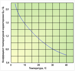
Figure 4.2 shows the dependence of the ratio Q25 / Qt
on temperature for an OO-membrane made of cellulose acetate.
Typically, the performance of RO membranes at constant pressure increases by approximately 3% per degree of temperature increase. The salt permeability of the membranes also increases in direct proportion to the increase in temperature, but the ratio between the salt and water fluxes penetrating the membrane remains essentially constant at different temperatures. Therefore, it is believed that the selectivity of the membrane is practically independent of temperature.
The selectivity of OO membranes for sodium chloride differs from the selectivity for other inorganic and organic solutes, so manufacturers of RO membranes must provide information on the selectivity of membranes for individual ions or substances.
Table 4.2 shows selectivity data for a typical composite RO membrane.
Table 4.2.
From the table it can be seen that the selectivity of retention of divalent ions such as calcium or sulfate is higher than that of monovalent ions such as sodium and chloride.
All tests described above, and accordingly data provided by RO membrane manufacturers, are carried out at low permeate recovery (low permeate recovery) to minimize the effects of concentration polarization. The parameters under which the OO membranes were tested must be indicated by the manufacturers in the certificate for the OO membrane.
Comparative conditions for testing 4040 series low pressure RO membranes for various RO membrane manufacturers are shown in Table 4.3 (as an example).
Table 4.3.
| Test parameter | Manufacturer | |||
| Hydranautics | FILMTEC | TORAY | Lewabrane | |
| NaCl concentration, mg/l | 1500 | 2000 | 2000 | 2000 |
| pH value | 6,5 - 7,0 | 7,0 | 7,0 | 7,0 |
| Temperature, o C | 25 | 25 | 25 | 25 |
| Degree of extraction of permeate, % | 15 | 15 | 15 | 15 |
| Working pressure, MPa (psi) | 1,05 (150)* | 1,55 (225) | 1,55 (225)* | 1,55 (225) |
* - passport working pressure of the OO-membrane.
5. CONCENTRATION POLARIZATION
We have already said that reverse osmosis refers to membrane mass transfer processes with transverse current. Therefore, as in any hydrodynamic process, the fluid adjacent to the membrane surface moves more slowly than its main flow. While the main flow may be turbulent, the near-surface fluid at the membrane remains laminar. This layer is called boundary layer. When water passes through the membrane (i.e., at the moment of separation of the source water flow into permeate and concentrate), almost all salt ions remain in the boundary layer near the membrane surface. This effect was called concentration polarization and is characterized by the concentration polarization coefficient:
β = C in / C m
Where, Cm
- salt concentration in the main stream; From to
- concentration of salt in the boundary layer.
Thus, the salt concentration in the boundary layer becomes higher than in the main stream. Due to the resulting concentration gradient, salt ions begin to diffuse back into the main stream.
The effect of concentration polarization, which increases the concentration of salts on the surface of the OO membrane, leads to an increase in the osmotic pressure on it, which reduces the specific permeate productivity of the membrane. This reduction can be estimated using the following equation:
J w = A∙(ΔP - β∙Δπ)
Table 5.1 shows the data on the influence of the effect of concentration polarization on the specific productivity and selectivity of the OO membrane at different salinity of the source water - TDS (2000, 5000 and 35000 mg/l) and initial values: specific productivity 34 l/m 2 ∙ h (20 GFD) and a pressure drop of 2.8 MPa (400 psi) with an initial selectivity (in the absence of the effect of concentration polarization) - 99%, i.e. β = 1.
Table 5.1.
| 2000 mg/l | 5000 mg/l | 35000 mg/l | |||||||
| Oud. name, Fw | R, % |
Oud. name, Fw |
R, % | Oud. name, Fw | R, % | ||||
| l/m 2 ∙h | GFD | l/m 2 ∙h | GFD | l/m 2 ∙h | GFD | ||||
| β = 1.0 | 34,00 | 20,0 | 99,0 | 34,00 | 20,0 | 99,0 | 34,00 | 20,0 | 99,0 |
| β = 1.1 | 33,83 | 19,9 | 98,9 | 33,66 | 19,8 | 98,9 | 31,11 | 18,3 | 98,8 |
| β = 1.5 | 33,15 | 19,5 | 98,5 | 31,96 | 18,8 | 98,4 | 19,21 | 11,3 | 97,3 |
| β = 2.0 | 32,30 | 19,0 | 97,9 | 29,75 | 17,5 | 97,7 | 4,25 | 2,5 | 84,0 |
The concentration polarization cannot be eliminated completely, but its effect can be minimized by reducing the thickness of the boundary layer. This is achieved by increasing the flow rate over the entire surface of the membrane or by installing various structural elements along the path of the water flow that will turbulize this flow (the so-called turbulators or turbulent inserts).
To overcome the occurrence of the effect of concentration polarization during the operation of systems, it is necessary to always follow the recommendations of the manufacturers of RO-membrane elements for the minimum flow and maximum degree of permeate recovery (permeate yield), especially when it comes to desalination of waters with high salinity or desalination of sea water. Most RO membrane manufacturers provide reverse osmosis design software to minimize the effects of concentration polarization and maximize permeate recovery (permeate recovery).
The decrease in the filtrate flux can be caused by several reasons - concentration polarization, adsorption, formation of a gel layer and clogging of pores. All these factors create additional resistance to transport across the membrane. The contribution of these effects to the total resistance to transport through the membrane is mainly determined by the type of membrane process and the properties of the filtered medium supplied to the membrane. Figure 5.1 schematically shows all types of additional resistances that appear on the membrane.  Ideally, the filtrate flow rate should only be affected by membrane resistance
R m However, if the membrane passes predominantly some of the components, and in some cases completely retains dissolved substances, this leads to the accumulation of molecules that are not able to penetrate the membrane near its surface. Thus, a highly concentrated layer of dissolved substances appears near the membrane, which prevents mass transfer. This resistance is called the concentration polarization resistance. Rcp.
Ideally, the filtrate flow rate should only be affected by membrane resistance
R m However, if the membrane passes predominantly some of the components, and in some cases completely retains dissolved substances, this leads to the accumulation of molecules that are not able to penetrate the membrane near its surface. Thus, a highly concentrated layer of dissolved substances appears near the membrane, which prevents mass transfer. This resistance is called the concentration polarization resistance. Rcp.
Polarization phenomena are observed in all membrane processes and accompany all separation processes. Over time, the concentration of solutes accumulating at the membrane surface can become very high and cause the formation of a gel layer. This gel-like layer (even very thin) creates a huge additional resistance to the flow of the original liquid ( Rg), sometimes leading to a complete cessation of the separation process. This phenomenon is very typical for high-molecular organic substances (for example, for protein solutions). A feature of the appearance of gel-like deposits on the membrane surface can be considered the process of precipitation on the membrane surface of some poorly soluble salts as a result of their concentration near the membrane surface. Such phenomena are most often encountered during reverse osmosis filtration of brackish water from deep artesian wells (deposits of sparingly soluble salts of calcium, magnesium (for example, carbonates or sulfates)).
In the case of porous membranes, some components may penetrate the membrane and block the pores. This additional resistance is called resistance. blocked pores
R p. And, finally, resistance can be caused by adsorption capacity of the membrane material
, Ra. Adsorption can occur both on the membrane surface and on the pore walls. As a rule, the contribution of this factor to the total resistance is small (except for the processes of separation of macromolecular substances having an asymmetric structure and an induced dipole moment).
A decrease in the filtration rate adversely affects the technical and economic indicators of both each membrane operation and the operation of the plant as a whole. Therefore, it is necessary to take certain measures to eliminate the causes leading to this phenomenon. This will be discussed below.
6. REVERSE OSMOSIS ELEMENTS
Reverse osmosis elements (RO elements) are formed from reverse osmosis membranes. According to the type of membrane used, OO elements differ in hollow fiber And spiral wound.
6.1. The first industrial RO elements with an asymmetric membrane based on hollow fibers made of aromatic polyamide with an inner diameter of 42 μm and an outer diameter of 85 μm, on the working surface of which a layer of an asymmetric membrane with a thickness of 0.1–1 μm was applied, were developed by DuPont (France). A standard 10 inch diameter OO element contained about 4.4 million of these fibers. They fit into the module in the form of a tube grid and their ends were sealed with epoxy resin.
  Hollow fibers with an asymmetric membrane can be combined into a thick-walled porous cylinder, the strength of which depends on the ratio of the outer and inner diameters. The fibers are arranged in parallel bundles. The gap between the fibers can be fixed with a helical thread wound around the fibers. The solution to be separated moves along the outer surface of the fibers. Under pressure, part of the liquid passes through the walls of the fibers, the permeate moves along the fiber channel. Provided that this ratio remains constant as both diameters increase, the mechanical strength of the cylinder will be constant despite the decrease in wall thickness, which increases the water flow through the wall. This makes it possible to create a membrane with a maximum surface area per unit volume, which at the same time is able to withstand high pressures without mechanical reinforcement. The record specific surface of membranes - 20,000 m 2 /m 3 was achieved by the already mentioned DuPont company in installations with membranes in the form of U-shaped hollow fibers.
  In this design (see Fig. 6.1), several hundred thousand fibers, folded in the shape of the letter U (item 4), are mounted inside a fiberglass pressure vessel. For what, cut in size along the length, the hollow fibers are collected in a bundle and bent in half by 180 degrees in the form of "loops" so that the "outputs" and "inputs" of the tubes are on the same side of the bundle. Then the ends of the tubes are filled with a special polymer adhesive. After the glue hardens, a part of it is cut off so that the entrances to the tubes are opened. Then this design is placed in a housing that directs the flow of water, and the filter element is ready!
The high specific surface area of the module has been achieved by using very small fiber diameters (typically hollow fibers have an outer diameter of 45-200 µm and a wall thickness of 10-50 µm). Purified water (see Fig.6.1, pos.1) under pressure is distributed radially inside the module by means of a porous or perforated collector (pos.6) running along the entire length of the module. On the outer surface of the fibers, the source water is separated under pressure into a concentrate (dirty water) and purified water (permeate), which passes through the walls of the fibers (pos. 4) and accumulates in the central channel (fibers), from where it enters the exit from the fibers. Then the permeate is collected by a porous disk (pos.9) and removed from the module (pos.2). The free ends of the fibers are fixed in an impermeable epoxy resin plate (pos.5). The concentrate is collected in the space between the outer surfaces of the fibers, passes through the porous plate (pos. 7) and is discharged through the hole (pos. 3) located in the inlet end plate of the module (pos. 8), in the same place as the source water inlet.
Fig.6.1. Principal design of an OO-element made of hollow fibers.
The numbers indicate: 1 - the input of the source water; 2 - output of purified water (permeate); 3 - concentrate output; 4 - hollow fibers from the OO membrane; 5 - epoxy resin lock; 6 - distribution pipe; 7 - porous disk; 8 - input end plate; 9 - output end plate; 10 - O-shaped gasket; 11 - thrust washer.
In general, the production and improvement of OO elements based on hollow fiber membranes is inextricably linked with DuPont.
In 1974, DuPont developed and introduced the first hollow fiber OO cells in the Permasep series. These were 4-inch cells with a capacity of 5.7 m 3 /day (1500 GPD) and a selectivity of 98.5% (under test conditions: solution - 30000 mg / l NaCl, pressure - 5.5 MPa (800 psi), permeate yield - 30%, temperature - 25°C).
Between 1974 and 1997, DuPont continuously improved the design and performance of its hollow fiber OO cells. So in 1992, two-pass modules (model 6880T) were introduced, having a productivity of 60.5 m 3 / day (16000 GPD) and a selectivity of 99.55% (under test conditions: solution - 35000 mg / l NaCl, pressure - 6.9 MPa (1000 psi), permeate yield - 35%, temperature - 25 ° C).
And just before the hollow fiber OO cell was discontinued, the SW-H-8540 was introduced as a single unit 8 ½" 40" long with 30.3 m3/d (8000 GPD) and 99 selectivity. 6% (under test conditions: solution - 35000 mg / l NaCl, pressure - 6.9 MPa (1000 psi), permeate yield - 35%, temperature - 25 ° C).
For seawater desalination in a single pass, between 1983 and 1997, DuPont developed Permasep SWRO hollow fiber OO elements with the following characteristics:
- permeate yield 30 - 50%;
- working pressure 6.9 - 8.3 MPa (1000 - 1200 psi);
- permeate quality< 500 мг/л при исходной морской воде с солесодержанием с 36000 - 45000 мг/л и температурой 17 - 38 о С;
- specific electricity consumption 3.7 - 8.2 kW * h / m 3.
Initially (in the 1970s), hollow fiber RO elements had some advantages over spiral type RO elements due to the simplicity of design and higher operating pressure (up to 8.3 MPa (1200 psi)), which made it possible to achieve a higher output permeate (up to 60% at an initial salt content of 38,000 mg/l and a temperature of 25°C).
However, a number of intractable shortcomings in the operation of hollow fiber membranes became the starting point, which made it possible to gradually oust OO elements based on them from the market. So, for example, it was found that in order to obtain a certain specific productivity, it is necessary to apply a pressure of 50% less to a spiral wound module than to a hollow fiber one.
The high specific surface area of the membranes is ultimately due to the small transverse dimensions of the channels through which the concentrate and especially the permeate move. This leads to a large loss of pressure in these channels. Therefore, the flow velocity along these channels is limited. As a result, in devices with hollow fibers, the difficulties associated with concentration polarization are strongly pronounced, which forces pretreatment to be especially careful, for example, the SDI index should be less than 3 (up to 5 is allowed for spiral wound modules).
In addition, sediments on the membranes during their fouling and fouling with hardness salts were difficult to remove due to low cross-flow rates and a relatively limited operating range of pH values (4 - 11).
And in the late 80s and early 90s of the last century, DuPont hollow fiber OO elements began to lose their positions in the market, giving way to spiral wound ones, the production technology of which began to develop rapidly due to fierce competition from such companies as: Filmtec / Dow , Rohm & Haas / Hydranautics, Toray, Fluid Systems / Koch, TriSep and Osmonics / General Electrics, etc. All this led to a decrease in prices for spiral wound modules, and for DuPont the production of hollow fiber OO elements becomes unattractive from an economic point of view vision. DuPont is curtailing their production.
However, the production of hollow fiber OO elements in the world has not completely disappeared. Several firms continue to produce such modules.
6.2. Spiral wound reverse osmosis elements.
Spiral wound reverse osmosis elements(another name roll reverse osmosis elements) have been widely used.  In this design ( see Fig.6.2
) on the central pipe (pos.7), through which the filtrate is discharged, a “sandwich” is wound, consisting of two OO membranes (pos.4), turbulator meshes (pos.5) and a gasket for collecting permeate (pos.6) . The key stage in the manufacture of spiral rolled membrane modules is the layer-by-layer laying of membranes and gaskets around the perforated permeate outlet tube, rolling and sealing this spiral structure. The compressive load that occurs during rolling causes the helix to compact and, as a result, the raw water pad and its adjacent layers to compress. After rolling, an outer coating of reinforced glass fiber (pos. 8) is applied to the resulting cylinder and antitelescopic covers (pos. 9) are installed.
In this design ( see Fig.6.2
) on the central pipe (pos.7), through which the filtrate is discharged, a “sandwich” is wound, consisting of two OO membranes (pos.4), turbulator meshes (pos.5) and a gasket for collecting permeate (pos.6) . The key stage in the manufacture of spiral rolled membrane modules is the layer-by-layer laying of membranes and gaskets around the perforated permeate outlet tube, rolling and sealing this spiral structure. The compressive load that occurs during rolling causes the helix to compact and, as a result, the raw water pad and its adjacent layers to compress. After rolling, an outer coating of reinforced glass fiber (pos. 8) is applied to the resulting cylinder and antitelescopic covers (pos. 9) are installed.
The water to be demineralized (pos. 1) flows parallel to the central pipe through the gap formed by the turbulator mesh (pos. 5) between the two active surfaces of the membranes (pos. 4) and is forced through the membranes. The filtrate (permeate) is collected inside the porous material (pos.6) and moves along it to the central pipe (pos.7). The concentrate (pos.2) is discharged through the perforation in the lid (pos.9).
Of course, the reverse osmosis membrane is the central technological element of the entire design, however, one cannot ignore other structural elements that can improve the mass transfer process and increase the energy efficiency of the reverse osmosis process.
Figure 6.2: Principal design of a spiral wound OO element.
 The numbers indicate
:
The numbers indicate
:
1 - source water;
2 - concentrate output;
3 - output of the filtrate (permeate);
4 - OO membrane;
5 - gasket (grid-turbulator);
6 - gasket for collecting permeate;
7 - perforated pipe for collecting permeate;
8 - outer coating of fiberglass;
9 - cover.
Despite its cylindrical configuration, the roll-type RO element is essentially a cross-flow mass transfer device, as the source water passes through the module in the axial direction, and the permeate moves in a spiral in the radial direction towards the perforated tube to collect it.
Over the past 20 years, the design and performance of spiral wound membrane elements have been greatly improved. Their productivity has more than doubled, and salt permeability has been reduced by almost three times. So, for example, FILMTEC managed to increase the membrane surface area in an 8-inch module from 28 m 2 (300 sq. ft) (1980) to 41 m 2 (440 sq. ft), and most importantly, that the paths for further increases in surface area are also visible. This can be achieved by reducing the thickness of the spacers, although it will be possible as long as the module structure remains rigid. But the appearance on the market of a new series - 16-inch membrane OO-elements dramatically increases the surface area by 4.3 times to 158 m 2 (1725 sq. ft).
In addition, the maximum working pressure of the spiral-wound RO membrane elements increased from 6.9 MPa (1000 psi) to 8.3 MPa (1200 psi), which increased the degree of permeate removal to 60% or more. This was made possible by making structural changes to the permeate and concentrate removal systems. Work continues to improve the design of connecting elements, including the end caps of the OO element.
Recent advances in the design of the spiral wound RO element are contributing to significant cost savings in the manufacture of reverse osmosis plants and making this technology more accessible and widespread in various parts of the world.  For some time now, all manufacturers of rolled membrane elements have come to a unified system of design dimensions that allow, if necessary, to replace an OO element manufactured by one company with another, similar in size and characteristics. In accordance with this system, RO elements for industrial and semi-industrial applications are produced with outer diameters of 2.5”; 4"; 8" and 16". The length of the modules varies.
Figure 6.3 and Table 6.1 show sketches and dimensions of reverse osmosis roll elements with outer diameters of 2.5” and 4”.
Table 6.1.
| OO module type | Outer diameter (D), mm (in) | Length (A), mm (in) | Connection dimensions | |
| Length (B), mm | Diameter (C), mm |
|||
| 2514 | 61 (2,5) | 356 (14) | 30 | 19 |
| 2521 | 533 (21) | |||
| 2526 | 660 (26) | |||
| 2540 (61-1016) * | 1016 (40) | |||
| 4014 | 99,4 (4,0) | 256 (14) | 27 | |
| 4021 | 533 (21) | |||
| 4025 | 635 (25) | |||
| 4040 (100-1016)* | 1016 (40) | |||

Figure 6.4 and Table 6.2 show sketches and dimensions of reverse osmosis roll elements with outer diameters of 8” and 16”.
Table 6.2.
* designations of domestic elements
In the following discussion, we will focus on the 8" helically wound RO element configuration, which is most commonly used in RO installations for industrial and municipal water supplies.
7. REVERSE OSMOSIS MODULES
OO elements are assembled into packages inside special holders (reverse osmosis modules) that provide both sealing of the ends of the OO elements and their “work”. Holders of OO elements, or whatever they are called high-pressure housings of reverse osmosis membranes, available for all sizes of 2.5” OO elements; 4"; 8” and 16” with different lengths and depending on the number of membranes placed in the housing, they can be single-cartridge and multi-cartridge (similar to filter holders for microfiltration). The material for the manufacture is reinforced fiberglass or stainless steel. 

During operation, the pressure of the treated water is perceived only by the body itself. Structurally, the holder for OO elements is a hollow cylinder with a number of sealing elements and end caps. Inlet/outlet nozzles for water inlet/outlet are placed either on the body shell or on the end plates. The figure shows a sectional view of the end face of a high-pressure composite housing for 4” diaphragms with and without an OO element installed.  IN The holder body can be sequentially placed from 1 to 8 OO-elements in such a way that the concentrate from each previous element is the source water for the next one.
The principal design of a typical composite high-pressure RO module containing three helically wound RO elements is shown in Figure 7.1. Source water (pos.1) enters the OO-module through a threaded hole located on the end inlet cover (pos.8), is distributed inside the housing of the OO-elements holder (pos.4) and is fed to the first OO-element (pos.5 ). To center the OO-element, a sleeve is inserted into the central drainage channel of the OO-element, which simultaneously serves as a plug for the permeate flow. In the OO-element, the source water is separated into permeate and concentrate. The first is collected in the central drainage channel (perforated pipe), and the second is sent to the next OO element. It also has a similar division. At the same time, the U-shaped gasket of the second OO element separates the flow of source water (concentrate of the first OO element) from the concentrate flow forming on the second OO element. Further, in the third. All OO-elements are interconnected along the central drainage pipe by bushings, which are equipped with O-shaped sealing rings recessed into the groove to prevent displacement during installation. The channel formed in this way collects all the permeate that was obtained from all the OO elements. Permeate is discharged from the last OO-element in the row in the same way through the sleeve, which is connected to the end cap (pos. 2). The concentrate from the last OO element is also discharged through the threaded hole in the end cap (pos.3). 
Figure 6.2: Principal design of a spiral wound OO module with three OO elements.
The numbers indicate
:1 - source water; 2 - output of the filtrate (permeate); 3 - concentrate output; 4 - housing of the OO module; 5 - spiral wound OO elements; 6-U-shaped gasket of the OO-element; 7 - bushing connecting the OO-elements for collecting permeate;
8 - inlet end cap; 9 - outlet end cap.
8. REVERSE OSMOSIS UNITS
Reverse osmosis has a very wide range of uses, which can be divided into two main groups:
- Solvent cleaning . In this case, the product is permeate.
- Solute concentration . In this case, the product is a concentrate.
The main use of reverse osmosis is water purification, mainly the desalination of brackish water and especially sea water in order to obtain drinking water. Another important field of application of reverse osmosis plants is the use of reverse osmosis as a stage of preliminary desalination of water in the production of ultrapure water (deionized water) for the semiconductor, medical and thermal industries.
At the stage of concentration, reverse osmosis is widely used in the food industry (concentration of fruit juices, sugar, coffee) and in the dairy industry (for the concentration of milk at the initial stage of cheese making), as well as in wastewater treatment (in electroplating for the concentration of galvanic waste).
8.1. The composition of the reverse osmosis plant. Now, let's focus on the purpose of the individual components of the reverse osmosis installation. On Fig.8.1
a general view of the OO-installation is given. On Fig.8.2
a schematic flow diagram of a typical single-stage reverse osmosis plant is presented.
Now, let's focus on the purpose of the individual components of the reverse osmosis installation. On Fig.8.1
a general view of the OO-installation is given. On Fig.8.2
a schematic flow diagram of a typical single-stage reverse osmosis plant is presented.
The first stage of the reverse osmosis process is the fine purification of the source water from mechanical impurities. Usually for  For this, cartridge-type filters are used, placed in single-cartridge or multi-cartridge filter holders, depending on the performance of the OO unit. The mechanism of operation of cartridge filter elements refers to microfiltration, namely to deep and / or surface filtration, i.e. mechanical impurities retained by the filter element accumulate inside the layer of the filter partition.
Water purified on cartridge filters is supplied to a high-pressure pump, the purpose of which is to achieve the pressure of the initial medium of the calculated pressure for the implementation of mass transfer processes occurring on semi-permeable reverse osmosis membranes. The selection of a high-pressure pump is based on its operating characteristics. In this case, the operating point of the pump should be in the range from 0.6 - 0.7 of its maximum performance.
If it is impossible to establish “parity” between the pressure and the pump capacity (and this happens most often), a bypass valve is installed between the suction and discharge pipes of the pump, with the help of which this operation is carried out (according to the readings of the rotameter and pressure gauge of the source water entering the reverse osmosis modules). Adjustment of the process of increasing the pressure of the source water is made once in the process of commissioning. During the operation of the RO-installation, only the control of the operating parameters of the source water is carried out.
From the high-pressure pump it enters the OO-modules, in which reverse osmosis elements
, on the OO membranes of which the separation of the source water into permeate and concentrate actually occurs. The concentrate leaving the reverse osmosis unit has a sufficiently high pressure and its transportation to the place of discharge or disposal does not cause any particular difficulties. The permeate pressure after a reverse osmosis plant rarely exceeds 1 atm. Therefore, most often it has to be fed into a storage tank, from where it is transported to further purification stages using a booster pump.
Several separate OO modules, placed in parallel or in series with respect to each other, form a cas-cad. The task of an engineer designing an OO installation is to assemble the modules in such a way as to optimize the system at the lowest cost of the product. The flow pattern in the module is one of the main factors determining the degree of separation achieved and the quality characteristics of the installation. In principle, there are two basic flow configurations used in single-stage or multi-stage reverse osmosis processes: 1) single pass system and 2) recirculation system (seerice. 8.3
- schemes of single-pass and recirculation systems).
single pass circuit recirculation circuit
In a single-pass system, the raw solution passes through a single module (single-stage system) or a system of modules (multi-stage system) only once, i.e. there is no recirculation here. In other words, the volumetric flow rate over the membrane decreases as you move from the entrance to the module to the exit from it. In multi-stage single-pass processes, this reduction in flow is compensated by a certain assembly of modules, the so-called conical cascade scheme (“herringbone”), as shown in rice. 8.4 a
. With this configuration, the plant can be designed so that the flow rate remains virtually constant. This system is characterized by the fact that the overall length of the path over the membrane and the pressure drop are large. Volume reduction factor, i.e. the ratio of the initial volume of raw material and the volume of concentrate, is determined mainly by the herringbone configuration, and not by the applied pressure.
Another configuration is the recirculation system shown in fig.8.4 b
. In this case, the raw material is compressed and pumped several times through the same stage, consisting of several modules. Each stage is equipped with a recirculation pump to optimize hydrodynamic conditions. There is only a small pressure drop in each stage where the flow rate and pressure can be adjusted. The feed recycle system is much more flexible than single pass systems and is preferred in microfiltration and ultrafiltration processes where strong concentration polarization and rapid membrane deposition can be expected. At the same time, for simpler tasks, for example, in the desalination of sea water, the use of a single-pass system is economically justified. 
All reverse osmosis units are equipped with an automatic control and monitoring system, which, as a rule, includes: a controller for controlling an OO unit, a conductometer, flow meters (rotameters), pressure gauges and pressure sensors.
9. OPERATION OF REVERSE OSMOSIS INSTALLATIONS
At the beginning of this section, the following two factors that exist in the operation of an OO installation should be noted:
- There is not a single OO installation that would work stably without the proper performance of all regulated work.
- Proper operation of the installation cannot always prevent the formation of stagnant water zones.
Let's understand the term proper or correct operation". During the operation of the OO-installation, this concept includes not only the careful execution of operations to maintain the technological parameters of the operation of the reverse osmosis unit, but also the systems for the preliminary preparation of initial solutions, and the replacement of filter elements, etc., etc.
A water treatment plant using reverse osmosis technology, as a rule, includes separate sections, which are shown in Figure 9.1. 
The first section, based on the experience of engineering practice, is equipped with equipment for pre-treatment of water, which is designed to prepare water to the requirements corresponding to the parameters recommended by manufacturers of reverse osmosis elements. After pre-treatment, water is supplied to the reverse osmosis unit, to reverse osmosis membrane elements placed in high-pressure housings. Under the influence of pressure on the surface of the membrane, the source water flow is divided into a product (permeate), which passes through the membrane, and into a given amount of waste (concentrate), which is discharged into the drain. The reverse osmosis permeate is sent to a further processing section (permeate post-treatment section), where equipment is placed to remove carbon dioxide from the permeate (decarbonization equipment) and / or the chemical composition of the permeate is adjusted (chemicals are dosed) to the required conditions of the main technological process.
9.1. Pre-treatment of water.
Choosing the right solution preparation method is the first step to reducing membrane fouling. Often, a lot of time and effort is spent cleaning the membranes, while the pre-treatment step of the stock solution is simply forgotten.
What does the term "correctly treated water" mean? We would like to draw your attention to the indicators of the content of individual ingredients in the source water, the values of which determine the operational characteristics of the installations and the reliability of their operation. The values of the content of these substances are indicated in Table 9.1
. For comparison, the same table shows the values of the same substances according to the requirements of SanPiN 2.1.4.1074.
Comparative indicators of water quality Table 9.1.
| Ingredient name | Units | Requirements in accordance with SanPiN | Source water requirements for RO installations |
| Suspended solids (turbidity), no more | mg/l | 1,5 | 0,6 |
| Total hardness, no more | mg-eq/l | 7,0 | 20 |
| Total salt content, no more | mg/l | 1000 | 50 000 |
| Color, no more | degree | 20 | 3 |
| pH value of source water, no more | 6 - 9 | 3 - 10 | |
| Colloidal index (SDI), no more | mg/l | - | 0,4 |
| Iron total, no more | mg/l | 0,3 | 0,1 |
| Oil products | mg/l | 0,1 | absence |
| Hydrogen sulfide and sulfides | mg/l | 0,003 | absence |
| Hard abrasive particles | mg/l | - | absence |
| Free active chlorine no more | mg/l | 0,3 | 0,1 |
| Permanganate oxidizability, no more | mgO 2 /l | 5,0 | 2,0 |
Differences in the requirements for source water according to SanPiN and for OO plants relate not only to organoleptic indicators of water quality, i.e. suspended solids and water color, but also oil products, surfactant
, oxidizability, colloids (iron, silicic acid). Therefore, much attention should be paid to the processes of preliminary preparation of source water before supplying water to the reverse osmosis unit.
Particular attention should be paid to the active chlorine content. The fact is that active chlorine has a very negative effect on reverse osmosis membranes and causes their destruction (destruction). Therefore, if chlorine-containing agents are used in the process of pre-treatment of water, it is necessary to introduce the stage adsorption water purification on active carbon
. The same process will help to reduce such an indicator as the oxidizability of water, which is responsible for the total content of organic compounds in the source water.
Depending on the degree of contamination of the source water, the methods of its treatment include: heat treatment, pH control, proportional dosing of complexing agents, biocides, coagulants using dosing pumps, aeration, iron removal, adsorption on activated carbon, mechanical purification and clarification of water, softening (Na -cationization), preliminary microfiltration or ultrafiltration, water disinfection using.
The dosing of chemicals in the process of preliminary water treatment is becoming an integral process for OO systems. Supply tanks for chemicals such as antiscalant, coagulant or chlorine or reducing agents (eg sodium metabisulphite) can themselves become sources of contamination. To prevent this, carefully review any recommendations from the RO system supplier or chemical manufacturer to determine the appropriate conditions for selecting tank operating conditions. Often the best approaches to solving this problem are: use of regular suppliers, complete replacement of reagent stocks and complete cleaning of tanks.
9.2. Operation of OO installations
There are no special problems in the operation of reverse osmosis plants with properly prepared water.
As we have already seen, the degree of saturation of the permeate with the ingredients present in the source water depends on the type of reverse osmosis membrane element used, as well as on the material of the membrane itself. Usually, after sufficiently properly prepared water, the degree of water desalination in a reverse osmosis plant is 95 - 98%, that is, the electrical conductivity of the permeate is in the range from 20 to 50 mS, or in terms of water resistivity 20 - 50 kOhm cm.
During the operation of the RO-unit, the following should be controlled: water pressure before and after prefiltration (before the RO-unit), pressure developed by the high-pressure pump (at the inlet to the RO-modules), concentrate pressure, concentrate, permeate and feed water flow, feed water temperature , specific electrical conductivity of the permeate and periodically the source water.
The preferred mode of operation of the OO plant is continuous. If the OO system cannot operate continuously, it must be programmed to automatically turn on for 15 minutes every 4 hours of inactivity to circulate flows in the system. This will help prevent the formation of deposits (primarily biofilms).
Table 9.2 provides some examples of common problems that may arise when operating an OO installation.
Table 9.2
| Problem | Cause | Troubleshooting options |
| Increased salt content of permeate | 1. Deterioration of water quality | 1. Reduce the proportion of permeate (increase in concentrate at a constant flow of source water) |
| 2. Decrease in concentrate consumption at a constant consumption of source water | 2. Increase the concentrate consumption at a constant consumption of source water | |
| 3. Low pressure of source water. | 3. Increase the pressure of the source water | |
| 4. The membranes are dirty | 4. Carry out chemical cleaning of membranes | |
| 5. Broken pump | 5. Replace the pump | |
| 6. Damaged membranes | 6. Replace membranes | |
| 7. Conductivity sensor dirty | 7. Clean and calibrate the sensor | |
| Reduced permeate consumption | 1. Decrease in temperature | 1. Increase temperature and/or pressure |
| 2. The membranes are dirty | 2. Carry out chemical cleaning of membranes | |
| 3. Damaged membranes | 3. Replace membranes | |
| 4. Low pressure source water | 4.See Further | |
| Low feed water pressure | 1. Clogged pre-filters | 1. Rinse or replace filter cartridges |
| 2. Low pressure source water | 2. Increase the pressure | |
| 3. Damaged solenoid valve at the inlet to the unit | 3. Replace solenoid valve |
With proper operation of RO systems, one cannot ignore such operations as standard chemical cleaning and disinfection of RO elements (surfaces of OO membranes). The following criteria should serve as a key to determining cleaning and disinfection cycles: plant pressure drop, capacity, flow rates, temperature, and microbiological contamination level. There are two general rules for determining when flushing and disinfecting an OO system is necessary:
- the first, when the performance of the OO installation decreases by 10 - 15%,
- the second, when there is a tendency to reduce the flow rate and increase the pressure drop.
With proper feed water pre-treatment, the membrane should last at least 3 years. However, performance and quality can degrade over time due to the formation of deposits or biological contaminants (we will discuss this in more detail in Section 10). Periodic chemical flushing is necessary to maintain the membrane in working order. The composition of the washing solution depends on the nature of the contamination, here are a few examples:
- In the event of a decrease in the quality of the permeate - a solution of 2% citric acid or 0.1% hydrochloric acid prepared on the permeate (pH ~ 3, t< 30 о С).
- In the event of a decrease in the productivity of the installation at a constant initial pressure, temperature, etc. - with a solution of 0.1% sodium dodecyl sulfate or Trilon B + 0.1% NaOH (pH< 10, t < 30 о С).
The reverse osmosis plant is flushed with a chemical wash unit, which is either part of the RO plant or can be a separate unit. All solutions for chemical washing are prepared on the permeate produced by the RO plant.
9.3. Water treatment after reverse osmosis installation.
We have already said that the pressure of the permeate after a reverse osmosis plant rarely exceeds 1 atm (0.1 MPa). Therefore, most often it is fed into the storage tank, from where it is transported with the help of a booster pump to further purification stages, where it is brought to the composition required by the conditions of the main technological process. For example, such stages can be:
- Decarbonization (removal of carbon dioxide from the permeate).
- Additional microfiltration cleaning on cascade cartridge filters.
- Disinfection of water using ultraviolet sterilization units.
- Correction of pH value and chemical composition by proportional dosing of various chemicals, also by means of bulk filters with corrective backfill.
- Adsorption treatment, either to improve organoleptic properties or to produce water with a low total organic carbon content.
- Deep desalination of water (OO-permeate) using ion exchange units (H-cationization, OH-anionation, mixed-bed filters) or using electrodeionization units.
The technological scheme of permeate post-treatment is selected based on its composition and requirements for purified water.
10. CONTAMINATION OF REVERSE OSMOSIS ELEMENTS AND MEMBRANES
10.1. General information.
What can be deposited on the membranes?
In order to understand this, we will use some concepts of the theory of hydration.
From theory  It is known that after the dissolution of substances in water around their particles: ions, molecules, small associates, micelles (large associates), hydrate shells are formed. Those. all particles (with rare exceptions), being charged, tend to attract and orient the dipole water molecules around them, i.e. distort or even destroy the original structure of water. The degree of manifestation of this trend depends on the size of the charge and the configuration of the particle (see figure). In this case, a two-layer hydration shell appears around the ions, polar molecules, and micelles, which consists of a dense layer of oriented water molecules ( layer A
) and loose layer ( layer B
) from semi-oriented water molecules.
It is known that after the dissolution of substances in water around their particles: ions, molecules, small associates, micelles (large associates), hydrate shells are formed. Those. all particles (with rare exceptions), being charged, tend to attract and orient the dipole water molecules around them, i.e. distort or even destroy the original structure of water. The degree of manifestation of this trend depends on the size of the charge and the configuration of the particle (see figure). In this case, a two-layer hydration shell appears around the ions, polar molecules, and micelles, which consists of a dense layer of oriented water molecules ( layer A
) and loose layer ( layer B
) from semi-oriented water molecules.
Dense layer of hydration shell ( layer A
), can be considered as consisting of water clusters linked by hydrogen bonds, the structure of which is specific depending on the nature of the hydrated particle. This layer is sufficiently strong, strictly ordered under the action of an electric field, and the water molecules in this layer are, as it were, “frozen”. During electrolysis, it moves along with the ion. The layer thickness is determined by the charge density of the ion (particle), i.e. the ratio of the charge of an ion (particle) to its (its) diameter. Some time later layer A
began to be called primary hydration layer
or primary hydration shell
.
Secondary hydration shell
(layer B
) is much less firmly bound to the ion, this is a kind of "melting" zone, intermediate between zone A
And zone C
, where the tetrahedral structure of pure water is preserved. Those. from zone B
V zone C
water molecules can move and vice versa.
The average lifetime of water molecules in a hydration shell depends on the nature of the particle, the concentration of dissolved substances, and temperature.
In 1951, after the coordination numbers for various electrolytes were established, it became possible to calculate the concentrations of electrolytes at which all the water present in the solution is included in the composition of the first hydration shells. Structurally, such a solution can be schematically represented as a system composed of only one layer of hydrated ions in contact with each other with their hydration shells ( zones A
). The boundary condition for the emergence of such a system (i.e., the concentration of the electrolyte in the solution) was called limit of complete hydration of an aqueous solution
(GPG). For different electrolytes, this concentration is in the range from 2.14 to 4.63 mol/l.  When the solution is diluted, water molecules begin to build a secondary hydration shell ( zone B
). The concentration of the solution at which all the available water enters the primary and secondary hydration shells was called limit of long-range hydration of an aqueous solution
(GDG
).
When the solution is diluted, water molecules begin to build a secondary hydration shell ( zone B
). The concentration of the solution at which all the available water enters the primary and secondary hydration shells was called limit of long-range hydration of an aqueous solution
(GDG
).
Consider what happens when the solution is concentrated (see figure). In a dilute solution, there are both GDG
(layer A + layer B
) and layer C
with the tetrahedral structure of pure water ( state I
). As the solution is concentrated (electrolyte is added to the solution), free water is first exhausted from layer C
(state II
), and then a layer of secondary hydration ( layer B
) up to the formation PIP
(state III
).
The reverse osmosis process is always associated with the concentration of solutions, so let's consider how the main characteristics of the membrane change - specific productivity ( G
) and holding capacity ( R
) with increasing concentration ( C1
).
As the concentration increases in the "water - solute - membrane" system, the following changes occur:
1 - all free water first passes into secondary hydration shells ( GDG
), and then to primary ( PIP
). The size of the hydrated ion decreases;
2 - the osmotic pressure of the solution increases proportionally C1
, which reduces the mass transfer driving force at constant operating pressure;
3 - the thickness of the bound water layer decreases due to competition for water between ions and polar groups of the membrane material in favor of ions.
Such a qualitative description leads to the assumption that both the specific productivity and the retention capacity should decrease as the concentration increases, which is observed in the experiment (see figure). 
From these graphs, one can clearly see the dependence that the decrease G
And R
begins when the solution "exhausts free water" (the value is reached GDG
), and to zero G
And R
come in a zone close to the value PIP
. Since one component passes through the membrane, and the second is delayed by it, a change in the concentration ratio in the volume of the initial solution necessarily occurs. After all, this is the goal of the membrane separation process, but these changes are very unevenly distributed in the volume of the solution. Therefore, there are so-called polarization phenomena on the membrane
, i.e. events occurring in a thin layer of the mixture being separated near the membrane surface due to its semi-permeability.
Since one component passes through the membrane, and the second is delayed by it, a change in the concentration ratio in the volume of the initial solution necessarily occurs. After all, this is the goal of the membrane separation process, but these changes are very unevenly distributed in the volume of the solution. Therefore, there are so-called polarization phenomena on the membrane
, i.e. events occurring in a thin layer of the mixture being separated near the membrane surface due to its semi-permeability.
Let us consider a typical picture of such a distribution over a component that is retained by the membrane.
The flow of the initial solution moves along the membrane with a volume flow W
and with the concentration of the delayed component So
. Under the action of a driving force (pressure gradient), a permeate flow penetrates the membrane G
with component concentration Wed< Со
. Due to the fact that the outflow of water occurs from the solution layer adjacent to the membrane, the concentration of the component in this layer increases as it approaches the membrane surface.
The figure shows a stationary process at w = const
, G = const
.
The thickness of the layer in which growth becomes noticeableWITH
, is δ
, and the maximum concentration on the membrane surface isCm
. Thanks toCm> Co
, there is a diffusion transfer of the component from the membrane to the core of the flowD*dc/dx
.
This nature of the change in concentration will be the same for any component retained by the membrane - inorganic ions and salts, water-soluble organic compounds, including high molecular weight ones, for colloidal and suspended particles.  It is clear that all baromembrane processes are accompanied by polarization phenomena. The differences will be that different substances behave differently during concentration: some may exceed the solubility limit and they will precipitate, some form spatial networks and turn into a gel, some begin to accumulate on the membrane due to adsorption and surface forces. The figure conventionally shows these situations in the form of additional resistance to mass transfer through the membrane.
Rp - pore overlap; Ra - adsorption; Rm - membrane;
Rg - gel layer; Rcp - layer of high concentration of dissolved substances.
In general, the intensity of formation and retention strength of deposits on the membrane depends on the porosity of the membrane, the charge and degree of hydrophilicity of its surface, the concentration of particles and impurities in the source water, their nature and size, temperature and pH value, the presence of conditions for adsorption, chemical interaction, crystal formation and the possibility of polymerization of substances on the membrane surface, as well as other factors. There is no general theory of the processes of formation of deposits on membranes, therefore, in engineering practice, experimental and operational methods of evaluation are most often used.
All deposits formed in the reverse osmosis module, as a rule, are divided into three large groups, which are distinguished both by their composition, structure and particle size of the sediment, and by the mechanism of deposit formation:
- Precipitation of suspended, colloidal particles and microorganisms.
- Precipitation of sparingly soluble compounds.
- Deposits of high-molecular organic substances.
Let's take a look at these three groups one by one.
10.2. Precipitation of suspended and colloidal particles. So to first group include precipitation of suspended and colloidal particles, as well as microorganisms. Those. The bulk of the sediments of this group consists of microparticles of organic and inorganic origin, coming both from the source water and formed during the preliminary treatment of the source water before reverse osmosis when it interacts with technological filter media, structural elements of the installation and with the atmosphere.
First of all, these are heterogeneous particles of various dispersity: colloidal and suspended inorganic and organic substances (various dust, metal oxides and hydroxides, sand - undissolved SiO 2 , clay and alumina, associates of organic substances and high molecular weight organic compounds (HMC), etc. ), as well as microorganisms that form a biofilm on the membrane surface.
Present in source water suspended microparticles with sizes from 1 to 25 microns,  can block (clog) channels between membrane packages, and at a high speed of movement along the membrane surface, they can have a kind of abrasive effect on it, i.e. can mechanically damage the barrier layer of the membrane. All this, as a rule, leads to irreversible damage to the membrane element.
In some cases, contamination of the pressure channel of the reverse osmosis element can lead to the failure of the device. So, for example, if the gasket-turbulizer-separator of the spiral membrane element is contaminated, the pressure drop from its different ends can increase until the element is destroyed due to the telescopic shift of the layers of the roll (spiral) relative to each other (the so-called " telescoping», from English telescoping). In this case, there will be a “leakage” of the source water into the permeate, which will be seen from a sharp sudden increase in the productivity of the installation and an increase in the salinity of the permeate.  Smaller microparticles and colloids, together with other deposits, which, as a rule, belong to the second group (which will be discussed below), and microorganisms form a deposit on the membrane surface that prevents its normal operation.
In practice, the amount of suspended particles in water is most often associated with the turbidity index, the analytical control of which is carried out by optical and photometric methods (GOST 3351). However, with regard to the resolution of these measurement methods, i.e. sizes of microparticles present in the analyzed water, then when using photometers (turbidimetric or nephelometric methods of measurement) it can be stated with confidence that their real resolution is 1-1.5 microns, and when visually determining turbidity (by the degree of turbidity of a column 10- 12 cm in a turbidity test tube) - more than 2-3 microns. ![]() Thus, when measuring the turbidity index, particles smaller than 1 µm, including colloids, are not registered by these methods. It should be noted here that, according to the results of many years of research in the operation of baromembrane apparatus, microparticles with sizes less than 0.45 microns are considered the most dangerous. Microparticles with such sizes can be "counted" using a laser microparticle counter, the operating principle of which is based on the method of determining the size of microparticles by the intensity of small-angle light scattering. Devices of this class are able not only to recognize the size of microparticles, but also to determine their number in a certain range. True, this method of measuring the amount of microparticles can only be laboratory, in addition to the fact that it is rather laborious and expensive.
Thus, when measuring the turbidity index, particles smaller than 1 µm, including colloids, are not registered by these methods. It should be noted here that, according to the results of many years of research in the operation of baromembrane apparatus, microparticles with sizes less than 0.45 microns are considered the most dangerous. Microparticles with such sizes can be "counted" using a laser microparticle counter, the operating principle of which is based on the method of determining the size of microparticles by the intensity of small-angle light scattering. Devices of this class are able not only to recognize the size of microparticles, but also to determine their number in a certain range. True, this method of measuring the amount of microparticles can only be laboratory, in addition to the fact that it is rather laborious and expensive.
In order to simplify the procedure for determining the amount of microparticles supplied to membrane plants with source water, at one time ASTM standards introduced colloidal index or sediment density index - SDI
(short for English Silt Density Index), which served as a characteristic of the degree of water contamination with mechanical and colloidal impurities and its suitability for supply to membrane plants. Currently per ASTM D-4189 SDI - index is a mandatory primary test of the quality of the source water, in the most general form showing the probability of the formation of sediments of colloidal and suspended substances that can contaminate the surface of the membrane elements.
The measurement of the SDI colloidal index is a rapid test that is performed daily (or as needed, for example, weekly - after a set of static data indicating the stability of the SDI colloidal index of the source water). Water sampling is carried out, as a rule, after cartridge filters before water is supplied to the membrane unit. The test can also be used to control the performance of clarifiers, pressure mechanical filters, both bulk and cartridge (mesh, depth, surface, etc.), iron removal filters, etc. The SDI method cannot be used to assess the service life of membrane elements, because there are no clear correlations between the composition of the source water and the value of the SDI index.
Silt Density Index (SDI-index) is an index of the density of suspended particles per unit volume of water - it determines the decrease in membrane performance due to the formation of contaminants on their surface, consisting of suspended and colloidal microparticles. The method for its determination is based on measuring the filtration time of a given volume of source water (usually 500 ml) through a calibrated microfiltration membrane with a pore size of 0.45 µm at a constant pressure drop across the filter of 0.207 MPa (30 psi) and a constant temperature. The choice of the pore size of the membrane - 0.45 μm is justified by the fact that the value of the equivalent diameter of microparticles of 0.45 μm is a transition from a dissolved state to a suspended one.
By values SDI 15
one can judge the complexity of the required pretreatment of water for membrane processes:
SDI< 5 Предварительная подготовка не требуется
SDI 5 - 10 One step pretreatment required
SDI > 10 Requires two-step preconditioning
SDI values for typical natural water sources:
| Source water type | Maximum SDI | Minimum SDI |
| Artesian | 5 | 2 |
| superficial | 175*) | 5 |
*) - for some open reservoirs, the value of the SDI index can reach 500.
By the value of the permissible critical value of the SDI index, one can judge the class of membrane elements (for leading manufacturers, the value of the SDI index of the source water ( SDI 15
) allowed: for artesian water - up to 5; for surface water - up to 18).
To reduce the SDI value, preliminary treatment of the source water is used. As a rule, well-known methods such as filtration and coagulation are used to remove suspended solids and colloids.
10.3. Precipitation of microorganisms - biofilm formation. 
Specialists who service reverse osmosis plants are constantly faced with such a phenomenon as the accumulation of some kind of mucus inside the membrane module, i.e. on the surface of the OO element and its holder. This is what lies on the surface ... The same mucus is located inside the OO membrane itself. A more correct name for this slime is biofilm
, i.e. colonies of microorganisms
fixed and developed on the surface of the membrane module.
We have already considered the process of biofilm formation in water supply systems in one of our publications, so here we should dwell on the features that are inherent in this process occurring on OO membranes. The biochemical effect of microorganisms on asymmetric semi-permeable OO membranes is considered to be more dangerous than the chemical destruction of membranes under the influence of oxidizing agents. Under certain conditions, biofilms can destroy the upper active layer of the membrane to its supporting layer, in which the pore size is commensurate with the size of bacteria. This is especially dangerous in the production of drinking water, since in this case pathogenic microbes and viruses from the source water can enter the filtrate (permeate).
The process of fixing microorganisms on the membrane surface is mainly determined by its properties: the material from which the membrane is made, the roughness of its surface, hydrophobicity and the surface charge of the membrane.
The design of helical OO membrane elements and the conditions on the membrane surface are ideal for the attachment, accumulation and growth of microorganisms. Why? First, the huge surface of the membrane; secondly, the height of the layer on the water-membrane interface is limited, and the layer itself is saturated with nutrients due to concentration polarization. Thirdly, in a narrow space of channels on turbulator grids separating membrane sheets, the water velocity is relatively low (about 0.1 m/s), and turbulence zones are limited. Finally, some polymeric materials, such as cellulose acetate, are a good breeding ground for microorganisms. This creates prerequisites for the development of colonies of microorganisms on the membrane surface, and their metabolic products can cause structural changes in the membrane polymer, especially in the structure of its thin active layer, which will lead to a deterioration in the characteristics of the desalination process.
In section 6.2 of this publication, we considered the fundamental design of a spiral wound reverse osmosis element. Let us briefly recall that in this construction ( see Fig.6.2
) on the central pipe (pos.7), through which the filtrate is discharged, a “sandwich” is wound, consisting of two OO membranes (pos.4), turbulator meshes (pos.5) and a gasket for collecting permeate (pos.6) .  To create turbulence on the grid (pos.5), the movement of the liquid is carried out, as a rule, along the diagonal of the grid rhombus (see figure), therefore, small stagnant zones can form near each cross strut of the grid, where the growth of biological fouling begins. In this case, hydrodynamic forces will be the main mechanism for transporting microorganisms to the membrane surface. And in the absence of water movement (for example, with a simple OO-installation), the transportation of cells directly to the membrane surface can be carried out due to Brownian motion or chemotaxis. The growth of biofouling will continue until the hydrodynamics of the flow change, i.e. the conditions of transportation and fixation of microorganisms will not change (for example, the presence of water hammer or a change in the composition of water).
This is the first step in the formation of a biofilm on the membrane surface. Next, the immobilization (fixation) of microorganisms on the membrane surface occurs due to the electrokinetic or hydrophobic interaction of the cell with the surface molecules of the membrane. After that, cell growth and reproduction begins both due to soluble nutrients in the source water and due to substances adsorbed on the membrane surface. This growth and reproduction of cells is accompanied by the release of an intercellular substance (polysaccharide), which anchors the cell to the surface, “clings” and fixes other cells to the substrate, and thereby stimulates microbial colonization of the membrane surface.
In addition, the resulting biofilm can act as a "trap" for suspended particles (they were discussed a little earlier), which, in turn, can quickly create dense deposits on the membrane.
There are a number of indicators that can change to help the operator determine that biofouling is the likely cause of a decline in reverse osmosis plant performance. These include:
- increase in pressure drop across the plant;
- decrease in water flow through the membranes (decrease in permeate productivity);
- decrease in the quality of purified water (increase in the specific conductivity of the permeate);
- the presence of slimy deposits on the inlet cartridge filters.
The number of genera and species of microorganisms present on the surface of OO membranes can be very diverse, and, in general, depends on the source of water supply, its organization and subsequent stages of pre-treatment before being fed to the OO membrane. Microorganisms present in the incoming source water may include bacteria, fungi, and yeasts. So, on the surface of the membrane, bacteria belonging to the genera are regularly found: Corynebacterium (lat. Сorynebacterium), pseudomonas (lat. Pseudomonas), actinomycetes (lat. Actinomyces), flavobacteria (lat. Flavobacterium), aeromonas (lat. Aeromonas), bacteria of the genus Arthrobacter and others. Of the fungi were found: penicilli (lat. Penicillium), mukora (lat.
Mucor), trichoderma (lat. Trichoderma), fusariums ( Fusarium), aspergillus (lat. Aspergillus), etc. And from yeast: candida (lat. Candida); pichia (lat. Pichia), lipomycetes (lat. Lipomyces), yeast of the genus Ambrosiozyma etc. Most often, the genus Pseudomonas (lat. Pseudomonas), which refers to " good producers» polysaccharides - the main component of mucus.
Typically, the total number of bacteria found on the surface of the OO membrane ranges between 106 and 108 cfu/cm 2 . But it is impossible to say in advance which of the genera and species will be present and prevail in the deposits on the OO membrane, even if the qualitative and quantitative microbiological composition of the source water is known. It is generally accepted that the fewer micro-organisms in the water before an RO installation, the less likely it is to biofoul. Therefore, usually for monitoring, the determination of the total microbial number (TMC) in the source water before reverse osmosis is widely practiced
. And as a universal means of protecting reverse osmosis from biofouling, reliable preliminary treatment of source water is considered.
It turned out that the best way limiting the growth of microorganisms is both the effective removal of the microorganisms themselves and the nutrients that they use in the course of their life. Therefore, for the preliminary treatment of source water, processes such as water disinfection with biocides, proportional dosing of coagulants and flocculants, and multi-stage filtration are used: mechanical filtration, catalytic iron removal, adsorption purification, and, if necessary, softening. The same processes are used to remove suspended particles from the source water.
Finally, it should be noted that an important role in the prevention of biofouling and removal of biofilm during the operation of the OO unit is played by the processes of periodic chemical cleaning and disinfection of OO modules using chemical washing units. We will talk about this separately ...
10.4. Precipitation of sparingly soluble compounds.
In this article in section 5, devoted to concentration polarization, we have already indicated that as a result of this phenomenon, “... precipitation on the membrane surface of some sparingly soluble salts as a result of their concentration at the membrane surface».
What sparingly soluble compounds can precipitate on the membrane surface? To answer this question, let us turn to the quality indicators by which source water is certified, namely ionic balance of source water
.
We have repeatedly pointed out that before designing a reverse osmosis system, a complete and accurate analysis of the source water must be performed. In addition to general indicators, such as: pH, turbidity, color, suspended solids content, permanganate oxidizability, alkalinity, total hardness, carbonate hardness, salinity (mineralization), contamination by microorganisms, the content of active and combined chlorine, etc., water analysis protocol must contain the name and concentration - of the following components in water:
| Cations: | mg/l | mg-eq./l | % | Anions | mg/l | mg-eq./l | % |
| Calcium Ca2+ | Bicarbonates HCO 3 2- | ||||||
| Magnesium Mg 2+ | Carbonates CO 3 2- | ||||||
| Sodium Na+ | Sulphates SO 4 2- | ||||||
| Potassium K+ | Chlorides Cl - | ||||||
| Iron Fe 2+ | Fluorides F- | ||||||
| Iron Fe 3+ | Nitrates NO 3 - | ||||||
| Manganese Mn 2+ | Nitrites NO 2 - | ||||||
| Aluminum Al 3+ | phosphates PO 4 3- | ||||||
| Ammonium NH4+ | Borates (for boron) | ||||||
| Barium Ba 2+ | Sulfides S 2- | ||||||
| Strontium Sr 2+ | Silicon by SiO 2 | ||||||
| Copper Cu 2+ | |||||||
| Zinc Zn 2+ | |||||||
| Sum of cations Ʃ | 100% | The sum of anions Ʃ | 100% |
Limits of detection of cations Ba 2+ andSr 2+ should be no more than 1 μg / l (1ppb) and not more than 1 mg/l (1ppm), respectively.
In this case, the total content of cations in water, expressed in mg-eq./l, should be equal to the total content of anions, expressed in mg-eq./l. The ionic balance of water converges only under this condition.
By combining the cations and anions present in the source water, and using the hint of Table 10.4.1, one can easily verify that in almost any water, the formation of sparingly soluble compounds is possible. The only question remains - will their concentration reach the limit at which these substances will begin to precipitate. The answer to it "lies on the surface" - the experience of operating reverse osmosis plants shows that situations arise when sparingly soluble salts are concentrated on OO membranes to a content above their solubility limit. A series of sparingly soluble salts was even compiled in order of decreasing problems with their deposits on the surface of membranes:
CaCO 3 > CaSO 4 >silicates> SrCO 3 > BaSO 4 > SrSO 4 > CaF 2 > CaSiO 3 > MgSiO 3 > Ca 3 (PO 4) 2 > Fe(HE) 2
Let's try to understand this series.
As a rule, all natural waters contain bicarbonates and carbonates, which for the most part determine the alkalinity of water or carbonate hardness. The process of formation of carbonates and bicarbonates is incorporated in the water cycle in nature: when precipitation falls on the ground, dissolution occurs in it carbon dioxide from the air and form carbonic acid ( H2CO3
), while its concentration in water is ~ 0.05%:
H 2 O + CO 2 → H 2 CO 3
In an aqueous solution, carbonic acid dissociates in two stages:
H 2 CO 3 ↔ H + + HCO 3 ¯;
HCO3¯ ↔ H + + CO3 2 ¯
As it passes through the soil, "sour water" (a weak solution of carbonic acid) washes out calcium carbonate from earthen rocks, as a result of which hydrocarbonates are formed. The water of most natural springs is close to saturation with calcium carbonate. Depending on the pH of the water, calcium carbonate is in equilibrium with calcium bicarbonate and dissolved carbon dioxide:
CaCO 3 + H 2 O + CO 2 ↔ Ca 2+ + 2HCO 3 ¯
or simplified in ionic form:
CaCO 3 + H + ↔ Ca 2+ + HCO 3 ¯
It has been found that if the pH value is below 8.3, the bicarbonate alkalinity (and carbonate hardness) will be balanced by a certain amount of carbon dioxide dissolved in the water. At a pH greater than 8.3, bicarbonates (HCO 3 -) will turn into carbonates (CO 3 2-). Those. when the pH value decreases, the equilibrium in the equation can be shifted to the right, and vice versa.
Thus, when the initial water is concentrated in the near-membrane layer, the equilibrium in the above reaction equation begins to shift to the left (water is removed from the layer). In addition, part of the free carbon dioxide, together with water, also passes through the OO membrane into the permeate. In this case, the pH value in the concentrate increases. As a result, the carbon dioxide balance in the near-membrane layer of water shifts - an excess of carbonate ions is formed, which interact with calcium ions.
From the foregoing, it follows that in order to avoid precipitation of calcium carbonate, the pH value in the concentrate stream must be lower than the pH value at which calcium carbonate in the concentrate stream is in equilibrium with saturation calcium bicarbonate - pHs.
The difference between the pH value of the concentrate and the saturation pH value ( pH
- pH
s
) are called Langelier index (LSI
-
Langelier
Saturation
Index
)
, the sign of which determines the carbonate stability of water and the possibility of calcium carbonate precipitation on the OO membrane. To prevent the formation of carbonate deposits on the membrane surface, the LSI index should always be negative. Those. when designing reverse osmosis plants for water with high alkalinity, it is necessary to use water pre-treatment methods that will help reduce the Langelier index, such as acidification (proportional dosing of the acid solution) and softening the source water or treating it with sedimentation inhibitors - dosing of anti-scaling agents. The operation of a reverse osmosis plant can be controlled by
Membrane reverse osmosis systems DRO series are used to purify domestic and drinking water from the compounds they contain: iron, manganese, silicon, boron, copper, lead, cadmium, organic compounds, pesticides, bacteria and viruses. Also, reverse osmosis systems are used in the treatment of boiler, process, underground and brackish waters, for the desalination of sea water.
DRO series systems have the following advantages:
- low power consumption;
- versatility of treatment and stability of the quality of purified water;
- ease of operation;
- high reliability (designed to work in harsh industrial conditions);
- environmental Safety;
- compactness;
- any level of automation;
- high ratio "price/quality";
- modern practical design;
- reverse osmosis plants are developed for a specific chemical analysis of source water, requirements and operating conditions;
- high quality workmanship using high-quality components from leading world manufacturers;
- short delivery time.
 Productivity on the purified water of installations of the return osmosis of the DRO series in standard execution from 0,05 to 30 m 3 /hour. Reverse osmosis units DRO8040K have a capacity of 30 to 150 m 3 /hour. Blocks of several reverse osmosis units DRO8K allow you to achieve productivity of 1000 m 3 / hour and more. These indicators indicate that reverse osmosis systems can solve a wide range of problems associated with water treatment and water purification at industrial and residential facilities.
Applications of reverse osmosis systems:
- food industry;
- Technological processes using high purity water (metalworking, electroplating, textile industry);
- Pharmaceutical industry and medicine;
- Thermal power engineering;
- Domestic and drinking water supply (hotels, offices and cottages);
- Water supply of shift camps;
- Desalination of sea and brackish water;
- Obtaining distilled water;
- Special areas of mechanical engineering;
- Microelectronics;
- Chemical industry;
- Metalworking;
- Plant growing and fisheries.
The DRO series includes four model ranges of systems with membrane elements: 2.5 inches(DRO-2540), 4.0 inches(DRO-4040) and 8.0 inches(DRO-8040 and DRO-8040-20…150). 
Depending on the application, Diasel installs the following modifications of DRO series reverse osmosis units:
- LE modification. Such water purification systems are equipped with low-pressure reverse osmosis elements, which provide high selectivity for most inorganic and organic substances.
- HR modification. These systems are equipped with highly selective reverse osmosis elements.
- NF modification. NF-systems are equipped with nanofiltration elements.
- LF modification. They include reverse osmosis or nanofiltration elements that are resistant to pollution by organic and colloidal substances.
The reverse osmosis systems of the DRO series use membrane elements manufactured by TORAY (Japan), Dow Chemical (USA) and CSM (South Korea).
The use of reverse osmosis units of the DRO series allows you to fully automate water treatment and carry it out around the clock. The complete set of installations allows you to quickly put them into operation, as well as work together with other systems for preliminary treatment (preparation) of source water. All reverse osmosis systems include the following components:
- carbon/stainless steel frame or body;
- High pressure pump;
- pre-filter 5 µm;
- low pressure switch at the inlet;
- permeate flow meter;
- concentrate;
- recycling;
- inlet/outlet manometer;
- a programmable logic controller that manages the operation of the system and controls the main parameters (quality of purified water, pressure (inlet / working), frequency of flushing, number of hours of operation, etc.);
- units for automatic hydraulic flushing and automatic rinsing with permeate (only systems DRO-8040 and DRO-8040-20…150).
The systems are also equipped with a circuit for reagent washing of membranes and a concentrate recirculation circuit (serves to return part of the concentrate flow to the system inlet and increase the overall permeate yield).
All main components of reverse osmosis units are mounted on a common stainless steel frame structure.
All pipelines, as well as control and shut-off valves, are made of stainless steel and (or) corrosion-resistant polymeric materials.
It is possible to change the configuration, as well as design and manufacture of reverse osmosis membrane systems of the DRO-2540, DRO-4040, DRO-8040 and DRO-8040-20…150 series in accordance with the wishes of the customer to solve specific problems of water treatment, for example: nanofiltration systems for partial softening, removal of sulfates and color of organic nature (humic and fulvic acids, tannins); ultra- and microfiltration systems for the removal of mechanical impurities, colloidal substances, as well as microorganisms (a more economical and reliable alternative to traditional sand filters); reverse osmosis systems for desalination of brackish and sea waters.
If the source water does not meet the requirements for water supplied to the membrane elements, reverse osmosis units are supplemented with a complex pre-treatment system, the composition and performance of which depend on the composition of the source water and the type of system.
Reverse osmosis systems DRO-2540/Leader series
The DRO-2540/Leader series system package includes:
- The unit is mounted in a single closed case, the front panel is closed with a glass door;
- Cartridge filter 1 µm (designed to protect the pressure membrane module);
- High pressure rotary vane type pump made of stainless steel (brass) ;
- Solenoid valve at the inlet to the reverse osmosis unit;
- Highly selective Vontron membrane elements;
- High-pressure membrane housings made of composite material (stainless steel);
- The dry running sensor is installed at the inlet to the unit;
- Pressure gauges - 4 pcs. (before the pre-filter, after the pre-filter, after the pump, after the highly selective membrane module);
- Rotameters - 3 pcs. (display of consumption in real time of concentrate, permeate and recycle);
- ;
Reverse osmosis systems DRO-2540 series
| Specifications | ||
|---|---|---|
| 2.5"x40" | |
| 0.05 - 0.30 m 3 / h | ||
| Permeate Recovery | 30-55 % | |
| Water temperature (design) | +10°С | |
| Selectivity | 95,0-99,0 % 1 | |
| Pressure range | 6.0-16.0 Ati 1 | |
| Power supply | 1х220-230V, 50Hz | |
| Control circuit | 1х220-230V, 50Hz | |
| Power of electrical equipment | 0.3-0.8 kW | |
| 2.3…2.8 kW/h*m3 | ||
| Inlet pressure (min) | 2.5 ati | |

1 depending on the type of reverse osmosis elements installed in the system and the total salinity of the source water
The DRO-2540 Series comes standard with:
- High pressure rotary vane type pump made of stainless steel (brass);
- Highly selective membrane elements Vontron 2540;
- 2540 High Pressure Composite Diaphragm Casings (Stainless Steel).
- The piping of the reverse osmosis system is made of high pressure PVC (PVC-U).
Reverse osmosis systems DRO-4040-Leader series
| Specifications | ||
|---|---|---|
| Membrane elements (size) | 4"x40" |
| Purified water (permeate) capacity | 0.33 - 0.70 m 3 / h | |
| Permeate Recovery | 50-65 % | |
| Water temperature (design) | +10°С | |
| Selectivity | 95,0-99,0 % 1 | |
| Pressure range | 6.0-8.0 ati 1 | |
| Power supply | 1х220-230V, 50Hz | |
| Control circuit | 1х220-230V, 50Hz | |
| Power of electrical equipment | 0.75 kW | |
| Specific electricity consumption | 1.4…2.9 kW/h*m3 | |
| Inlet pressure (min) | 3.0 ati | |

1 depending on the type of reverse osmosis elements installed in the system and the total salinity of the source water
The DRO-4040/Leader Series comes standard with:
- The unit is mounted in a single closed case, the front panel is closed with a glass door.
- The “leader” package includes a simplified controller that has the following functions: dry-running protection, automatic shutdown by high permeate pressure or by float switch, indication of the electrical conductivity of water at the inlet and outlet of the installation, display of the parameters of the operation of the reverse osmosis unit;
- Solenoid valve at the inlet and outlet of the reverse osmosis system.
- The dry run sensor is installed at the inlet to the unit.
- Mechanical cleaning filter 1 micron.
- Pressure gauges with hydraulic filling - 4 pcs. (before the pre-filter, after the pre-filter, after the pump, after the highly selective membrane module).
- Rotameters - 3 pcs. (displaying real-time consumption of concentrate, permeate and recycle).
- To control the operating pressure, stainless steel needle valves or GF diaphragm valves are used.
- The unit is provided with a continuous recirculation line
- The reverse osmosis unit has access to the chemical washing of membrane elements.
- The piping of the reverse osmosis system is made of high pressure PVC (PVC-U).
Reverse osmosis systems DRO-4040 series
| Specifications | ||
|---|---|---|
| Membrane elements (size) | 4"x40" |
| Purified water (permeate) capacity | 0.45 - 2.50 m 3 / h | |
| Permeate Recovery | 45-70 % | |
| Water temperature (design) | +10°С | |
| Selectivity | 95,0-99,0 % 1 | |
| Pressure range | 6.0-22.0 ati 1 | |
| Power supply | 3 x 220-230V, 50Hz | |
| Control circuit | 1 x 220-230V, 50Hz | |
| Power of electrical equipment | 1.5 - 4.0 kW | |
| Specific electricity consumption | 1.0…1.4 kW/h*m3 | |
| Inlet pressure (min) | 2.5 ati | |

1 depending on the type of reverse osmosis elements installed in the system and the total salinity of the source water
The DRO-4040 Series comes standard with:
- The unit is mounted in a single closed case, the front panel is closed with a glass door.
- The reverse osmosis unit has a built-in logic controller that displays the values of the electrical conductivity of the source and purified water, the operating mode of the unit, and also performs a smooth start of the system and hydraulic flushing of the membranes.
- The kit includes a frequency converter
- Solenoid valve at the inlet and outlet of the reverse osmosis system.
- The dry run sensor is installed at the inlet to the unit.
- Mechanical cleaning filter 1 micron.
- Multistage centrifugal pump high pressure Grundfos;
- Highly selective membrane elements Vontron 4040, Toray 4040;
- 4040 high-pressure diaphragm casings made of composite material (stainless steel).
- Pressure gauges with hydraulic filling - 4 pcs. (before the pre-filter, after the pre-filter, after the pump, after the highly selective membrane module).
- Rotameters - 3 pcs. (displaying real-time consumption of concentrate, permeate and recycle).
- Solenoid valve for quick hydraulic flushing of membranes. (flash-wash)
- To control the operating pressure, stainless steel needle valves or GF diaphragm valves are used.
- The unit is provided with a continuous recirculation line
- The reverse osmosis unit has access to the chemical washing of membrane elements.
- The piping of the reverse osmosis system is made of high pressure PVC (PVC-U).


Reverse osmosis systems DRO-8040 series
| Specifications | ||
|---|---|---|
| Membrane elements (size) | 8"x40" |
| Purified water (permeate) capacity | 2.0 - 15.0 m 3 / h | |
| Permeate Recovery | 60-75 % | |
| Water temperature (design) | +8°С | |
| Selectivity | 95,0-99,0 % 1 | |
| Pressure range | 7.0-22.0 ati 1 | |
| Power supply | 3 x 380V, 50Hz | |
| Control circuit | 1 x 220-230V, 50Hz | |
| Power of electrical equipment | 4.0 - 18.5 kW | |
| Specific electricity consumption | 0.9…1.2 kW/h*m3 | |
| Inlet pressure (min) | 2.5 ati | |

1 depending on the type of reverse osmosis elements installed in the system and the total salinity of the source water
The DRO-8040 Series comes standard with:
- The dry run sensor is installed at the inlet to the unit.
- Mechanical pre-filter (1µm multi-cartridge filter)
- Grundfos high pressure multistage centrifugal pump;
- Pressure gauges with hydraulic filling - 4 pcs. (before the pre-filter, after the pre-filter, after the pump, after the highly selective membrane module).
- Rotameters - 3 pcs. (displaying real-time consumption of concentrate, permeate and recycle).
- Solenoid valve for quick hydraulic flushing of membranes. (flash-wash)
- To control the operating pressure, stainless steel needle valves or GF diaphragm valves are used.
- The unit is provided with a continuous recirculation line
- The reverse osmosis unit has access to the chemical washing of membrane elements.
- The piping of the reverse osmosis system is made of high pressure PVC (PVC-U).

Reverse osmosis systems DRO-8040-20…150 series
| Specifications | ||
|---|---|---|
| Membrane elements (size) | 8"x40" |
| Purified water (permeate) capacity | 20.0 - 130.0 m 3 / h | |
| Permeate Recovery | 67-85 % | |
| Water temperature (design) | +8°С | |
| Selectivity | 95,0-99,0 % 1 | |
| Pressure range | 7.0-22.0 ati 1 | |
| Power supply | 3 x 380V, 50Hz | |
| Control circuit | 1 x 220-230V, 50Hz | |
| Power of electrical equipment | 18.5 - 160.0 kW | |
| Specific electricity consumption | 0.8…1.1 kW/h*m3 | |
| Inlet pressure (min) | 2.5 ati | |

1 depending on the type of reverse osmosis elements installed in the system and the total salinity of the source water
The standard package of DRO-8040-20…150 series systems includes:
- The entire unit is mounted on a powder coated black steel or stainless steel frame.
- The reverse osmosis unit has a built-in logic controller with an operator touch panel, which displays the values of the electrical conductivity of the source and purified water, the operating mode of the unit, and also performs a smooth start of the system and hydraulic flushing of the membranes. The controller also keeps statistics of the system operation parameters, and is able to issue statistical data for various periods of time.
- At the request of the customer, it is possible to control the system from the top level of customer automation.
- Solenoid valve (or shutter with electric (pneumatic) drive) at the inlet and outlet of the reverse osmosis system.
- The dry run sensor is installed at the inlet to the unit.
- Mechanical pre-filter (1µm multi-cartridge filter)
- Grundfos high pressure multistage centrifugal pump;
- Highly selective membrane elements Toray 8040;
- 8040 high-pressure multi-place diaphragm casings made of composite material (stainless steel).
- Hydro-filled pressure gauges - 4 pcs. (before the pre-filter, after the pre-filter, after the pump, after the highly selective membrane module).
- Rotameters - 3 pcs. (displaying real-time consumption of concentrate, permeate and recycle).
- Solenoid valve for quick hydraulic flushing of membranes (flash-wash).
- To control the operating pressure, stainless steel needle valves or GF diaphragm valves are used.
- The unit is provided with a continuous recirculation line.
- The reverse osmosis unit has access to the chemical washing of membrane elements.
- The piping of the reverse osmosis system is made of high pressure PVC (PVC-U).


SHELL-GS version available for DRO-2540 and DRO-4040 series


Characteristics of reverse osmosis systems of the DRO series
| Name | Productivity (nominal / design), l/h* | Series DRO-4040/Leader ** installed pump capacity of the system depends on the type of membrane elements usedFor DRO-8040-5÷7 systems | 1,5 | No | Yes | 340 | 75x90x165 | |
|---|---|---|---|---|---|---|---|---|
| CIP8-560 | For DRO-8040-8÷10 systems | 2,2 | No | Yes | 560 | 91x115x190 | ||
| CIP8-780 | For DRO-8040-12÷15 systems | 4,0 | No | Yes | 780 | 91x130x205 | ||
| CIP8-1140 | For DRO-8040-20÷24 systems | 5,5-7,5 | No | Yes | 1140 | 120x140x180 | ||
| CIP8-1500 | For DRO-8040-30÷150 systems | 7,5 | No | Yes | 1500 | 150x120x280 |


Related posts:
 Sandwiches in proper nutrition Sandwiches without bread for weight loss
 Michael Rockefeller: biography, versions of the disappearance Rockefeller's missing expedition from the cycle of the mystery of the century
 Arthur Conan Doyle Historical Series
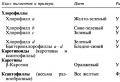 Why is carbon dioxide essential for photosynthesis?
 Omelette recipe with milk and egg in a lush pan How to cook an omelette in milk in a pan


