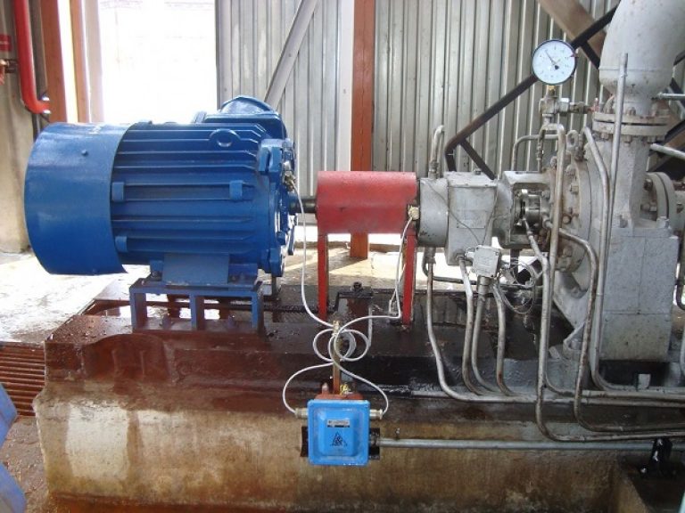
Electric centrifugal console pump. Console pump: technical specifications of this type of equipment, device, video and photo.
The lion's share of all the pumps manufactured in the world are cantilever pumps of various types and designs. According to experts, published at different times in specialized publications related to pumping topics, the number of console pumps in pieces is from 59 to 72% of the total fleet of pumps manufactured in the world. This figure is due to the simple design of the console pump compared to other types of pumps. The elementary principle of a cantilever pump ensures its widespread use both in public utilities and in complex fluid supply systems for military equipment and spacecraft.
Externally, the design of the console pump is very similar to many others, not a specialist can easily be mistaken in appearance, especially if you rely on the name "console" and look for the console in the design. In any machine builder’s manual about a console pump, the following is literally written:
"The cantilever pump is connected to the electric motor through an elastic coupling. In KM type pumps, the impeller is mounted on the end of the elongated motor shaft ..."
It would be reasonable to assume that it is called a cantilever because its working part is located cantilever relative to the bed. And this is true with some small cantilever pumps. However, in most cases, the working part of the console pump at its farthest point from the drive is rigidly fixed to the pump housing, and there should be no talk of any console. An example in the figure is a console pump of the brand K65-50-160 / 4:
This is a classic cantilever pump, and it has no visible console. So why is it called a console?
And it is called so not by chance. The fact is that the cantilever part in such a pump is located inside the casing, and is an impeller cantilevered to the shaft.
The principle of operation of console pumps
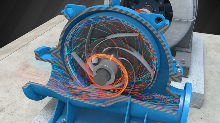
The impeller of the console pump is a drum consisting of two disks and partitions located at a certain angle. The drum is placed in the cavity and rotated by a shaft, the bearing assembly of which is protected from liquid inside the cavity. Thus, the drum (impeller) is located cantilevered on the shaft inside the pump housing. The cavity in which the pump impeller is located has two holes - one on the opposite side of the shaft (in the center, in the region of the shaft axis), and the second on the circumference of the housing. The first hole serves to supply the working fluid to the impeller of the console pump, the second - to drain the fluid under pressure. The fluid pressure arises as a result of the rotation of the impeller and the resulting centripetal acceleration in the fluid rotated by the walls of the impeller - the vanes of the cantilever pump. Hence the name of one of the types of console pumps - " centrifugal cantilever pump".
Classification of console pumps:
Console pumps are distinguished by:
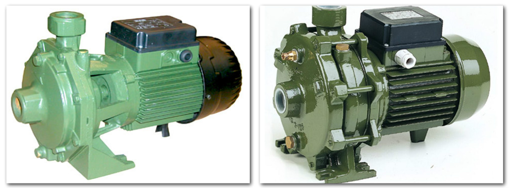
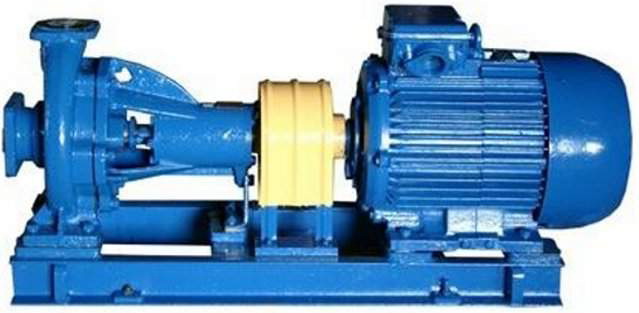
- "K" - the main version of the console pumps. Performed horizontal execution based on the housing of the pump unit. The drive takes place via an elastic coupling.
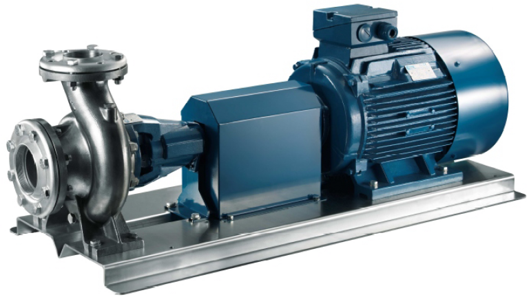
- "KM" - console monoblock. The impeller is not located on its own shaft, as in the pumps of the "K" series, but on the elongated shaft of a special induction motor.
- "KMP" - monoblock boosting pump. In fact, the same monoblock console, but is designed specifically for use in the housing sector, in residential buildings.
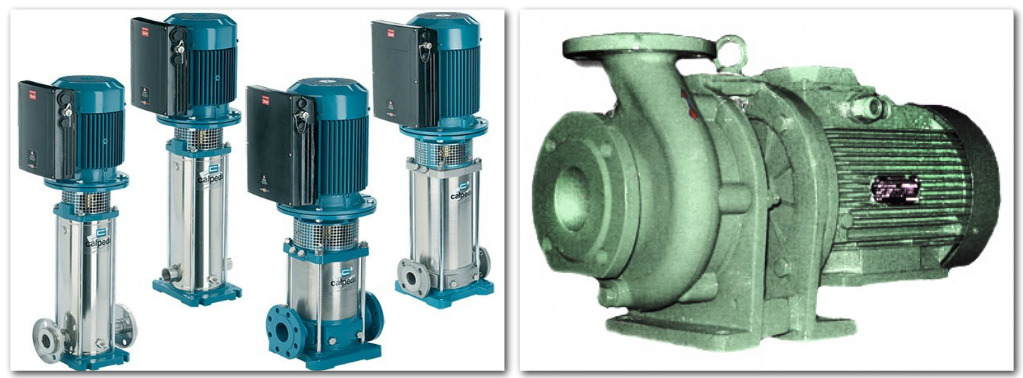
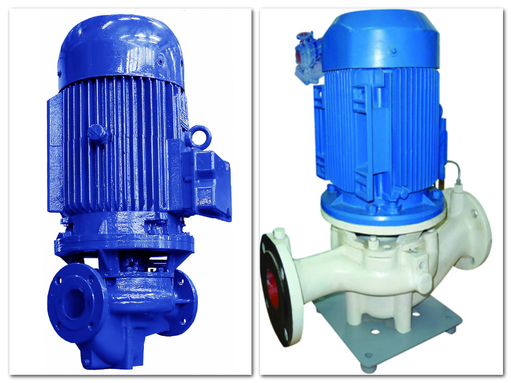
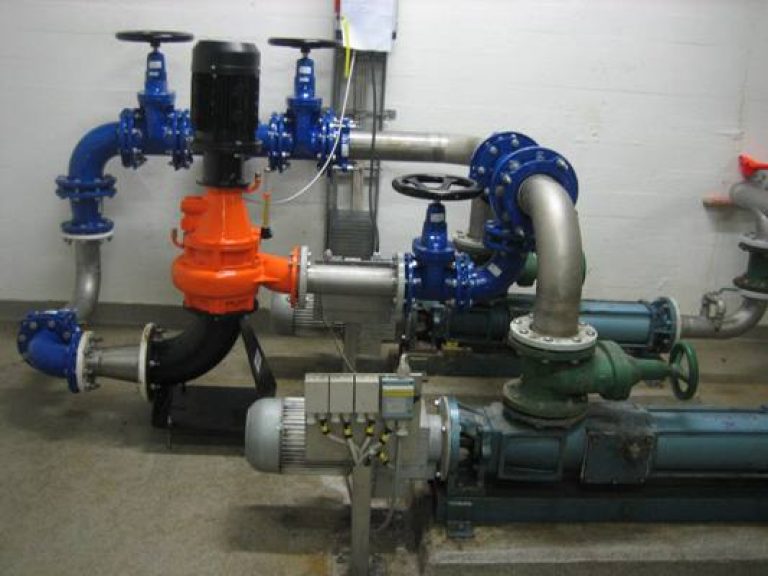
- KML (CVC) is a linear centrifugal cantilever pump with a vertical impeller axis and a linear arrangement of the suction and outlet openings.
Console Pump Material
For the manufacture of the impeller of the cantilever pump, structural and alloy steels are used, as well as gray cast iron. For pumping special (aggressive) liquids, alloys are used that are adapted to the effects of the pumped medium. The casing material of the cantilever pump can also be cast iron, and aluminum, and made of stainless steel.
As the shaft seal of the cantilever pump, glands and cuffs of various types are used, depending on the type of pumped liquid and its temperature. Serially produced console pumps "K" and "KM" are designed to work with liquids with temperatures up to 85 degrees, special pumps are used to pump hotter liquids.
In agriculture and industry, from time to time there is a need for transportation of liquid media. In order to pump out waste water or other liquids, special pumping equipment is used. I will tell you where the centrifugal cantilever pump is used, what are its design features and what varieties can be bought.
Hardware Overview
Over 60% of pumps manufactured worldwide are cantilever centrifugal units. Despite the fact that all these units are used to perform various tasks, their functional purpose boils down to pumping a liquid medium.
The wide distribution of console-type units is due to:
- constructive simplicity;
- long service life;
- high maintainability and ease of do-it-yourself preventative maintenance;
- effectiveness of application.
Due to its operational features, single-acting cantilever water pumps are widely used for pumping a wide range of liquid media, starting with domestic systems autonomous water supply and ending with complex industrial complexes.
Console Pump Application
The scope of application of console pumps extends to the following processes:
- Flue gas supply to treatment plants;
- Pumping aggressive and abrasive suspensions;
- Transfer of oil sludge;
- Transfer of sludge and pulp;
- Transfer of sludge and pulp with acid content;
- Pumping liquids from natural and artificial reservoirs;
- Pumping bottom sediments from cesspools, septic tanks, cisterns, pits, etc .;
- Drainage of soils (irrigation works);
- Shipment of bulk cargo from railway and water transport;
- Shipment of raw materials and waste from the metallurgical industry.
Varieties of equipment and their configuration
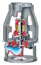
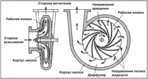
When passing through the pump, the liquid medium receives acceleration greater than at the inlet. In order to convert the acceleration of the liquid medium into pressure, a spiral outlet (1) with a guide apparatus (3) is installed at the outlet of the unit. Liquid from the pump enters the converter through the inlet (2).
After passing into the hole, the fluid swirls in the cavity of the cochlea. Due to the variable cross-section of the cavity of the spiral outlet, acceleration is converted to pressure. At the end of the process, the liquid medium under pressure leaves the spiral outlet through the discharge pipe (4).
The main element in the design of the pump is the impeller (4), which rotates the fluid into motion. The impeller is rigidly fixed on the shaft (9), which, in turn, is attached to the motor pulley.
To ensure uniform rotation of the wheel, the shaft on both sides is enclosed in closed needle bearings (11), which, in turn, are attached to the unit body (2) through damping pads on the support bracket (10). The pump housing is most often made of cast iron, since this alloy is resistant to vibrating effects and does not require repair for a long time.
Special openings may be provided in the housing for the prophylactic replacement of lubricants. Household models that are known as sewer submersible pumps, are not designed for heavy loads, and therefore do not need prevention.
Together with the electric motor, the cantilever pump is attached to the welded metal pad through the mounting eyes. The unit together with the engine works as a single functional unit.
Varieties of centrifugal cantilever pumps
There are several varieties of cantilever pumps on the market. The operating instructions and specifications.
| Artwork | Varieties of pumps and their features |
 | Single and multi-stage modifications. By the number of impellers, one-wheel (single-stage), two or more wheel (multi-stage) modifications are distinguished. The more wheels used in the design of the unit, the more pressure it can give at the outlet. |
 | High, medium and low pressure modifications. In accordance with the pressure at the outlet, they differ:
|
 | Horizontal and vertical modifications. In accordance with the location of the unit body, horizontal and vertical modifications are distinguished. This feature determines the type of installation. |
 | Modifications with bilateral and unilateral supply of medium. In accordance with the method of supplying water to the impeller, they differ with two-way supply and one-way fluid supply. This design feature only affects the ease of installation of equipment. | Submersible devices, in the photo on the left, are located directly in the pond. In this case, the pipeline is arranged to drain the liquid medium.
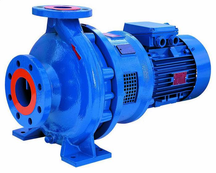
| Artwork | Classification according to design | |
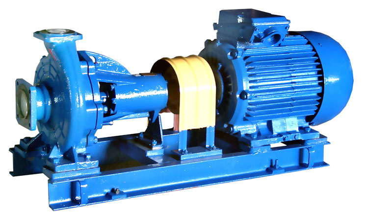 | K-type cantilever pumps This is the most common equipment modification, which is characterized by horizontal execution. The impeller is mounted on its own shaft, which is driven by the drive through an elastic coupling. | The KM type cantilever pump is characterized by less vibration during operation.Console monoblock linear (KML). This type of pump has a vertical axis of the impeller and a linearly arranged suction and outlet. |
The cost of equipment and what it depends on
The price of pumps is determined by such parameters as engine power, pressure characteristics, power consumption, degree of vibration and noise. In addition to these factors, the price is determined by the brand of the manufacturer. It is clear that products of domestic manufacturers will be more affordable than the expensive console pumps Grundfos or Pedrollo.
On average, the price of domestic equipment with an engine power of 1.5-2.5 kW is from 6 to 15 thousand rubles. Prices are valid for the spring of 2017. With increasing power, the cost of the pump increases.
To summarize
Now you know what a cantilever pump is, how it is designed and what it is for. I also recommend watching the video in this article. And if you have any questions, ask them in the comments.
Among the total volume of pumping equipment produced by the world industry, console pumps account for 60-70%.
This technique is popular due to its simple construction, high work efficiency and excellent maintainability.
1 Classification and descriptions
The cantilever pump is designed for work with lightly contaminated and clean liquids that do not contain mechanical impurities. The permissible content in the working environment of abrasive substances is 0.1%, and their size is up to 0.2 mm.
Console pumps are used in the following areas:
- irrigation and irrigation systems;
- water supply;
- utilities;
- chemical production.
The cantilever pump comes in four varieties, which depends on the design:
- K - standard units: they have a horizontal housing, a wheel and a drive are connected by an elastic coupling.
- KM - pumps are cantilever monoblock, in which there is no separate impeller shaft.
- KMP is a cantilever monoblock boosting device, which was created to work in public water supply and almost does not differ from KM.
- KML - console linear devices that have a vertical impeller axis and a linear arrangement of the supply and intake pipes.
The most popular are console type K pumps, which are industrial equipment.
2 Principle of work
The main functional unit of the centrifugal cantilever pump is the impeller, with which the working medium is pumped.
The wheel looks like a drum, which consists of two parallel disks that are connected by plate partitions. The impeller mounted in the working cavity takes on a rotational moment from the shaft, which leaves the electric motor. The wheel is fixed on the shaft with a bearing assembly that is protected from liquid.
The inner part of the housing where the drum is located has openings for supplying and absorbing working fluid. The principle of operation of the unit is very simple - with the help of the suction hole, water enters and the blades of the wheel take it, which during rotation accelerates the liquid and feeds it through the feed hole.
2.1 Construction
The purpose of the unit affects the materials from which its parts are made. In equipment for general industrial purposes, wheels from alloy steel are used, sometimes from cast iron. The cantilever apparatus for conveying chemical liquids is equipped with a drum made of alloys that remain unharmed in the pumped medium.
The case of the device is made of cast iron, aluminum, steel or stainless steel. The material for the production of oil seals, cups and rings is selected depending on t˚ the working fluid. The most common console pump of type K works with a liquid of not more than 85 ° C.
3 Fluid transfer equipment
The cantilever pump for water is a reliable and high-quality unit. It is used for pumping cold or hot water. The efficiency of these devices is 60-80%, but it depends on the engine power and model. The cantilever monoblock pump has both a stuffing box and a mechanical seal.
Console pumps are of two types: vertical and horizontal. The horizontal cantilever axis of rotation is horizontal. The location of the axis of rotation affects the supports and devices inside the unit. The axis of rotation can be horizontal, vertical, at an inclined horizon.
3.1 Type K pumps
The enterprises use electric pumps for type K water (for example, they use a console pump K 8 18, K 20 30, etc.). The running gear of the console pumps for water has a shaft that rests on the bearing on which the impeller is located. And it also has a compensation chamber, which helps to avoid water leakage at high pressure.
The front and rear seals prevent fluid from entering inside and out. Leaks through the gland are not cleaned and are an additional lubricant, which protects the engine well from overheating. The shaft that is located above the oil seal is protected by the sleeve against wear.
3.2 One-piece pumps
The difference between monoblock console pumps is that the impeller is integrated on the shaft end. These powerful units are called KM type pumps. These units are used in enterprises in engineering. Among the shortcomings of this powerful unit, it is worth noting that it has a large size, large weight and a very short-lived seal, as a result of which the unit needs constant inspection and regular repair. And the repair of the KM electric pump is longer, laborious and expensive than type K.
The most common monoblock units: KM 50 32 125, KM 80 50 200, KM100 80 160, KM 65 50 160.
The electric pump KM 65 50 160 is characterized by very small dimensions and low weight. This technique can be integrated into a ready-made working system.
Technical characteristics of KM 65 50 160:
- productivity - no more than 30 cubic meters;
- head - up to 30 m;
- engine power - 5.5 kW;
- permissible temperature of the working fluid is from -20˚С to 100˚С.
3.3 K 20 30
The centrifugal cantilever pump K 20 is equipped with a horizontal axial inlet of the working medium. K 20 is designed for pumping liquids in stationary conditions. Shaft seal - single face, single or double stuffing box.
The K 20 30 unit has a large area of \u200b\u200buse: heat pipes, water pipes, pumping stations industrial, rural and urban water supply. The K 20 unit is not used in fire hazardous and explosive rooms.
Technical characteristics of K20 30:
- head - 30m;
- giving - 20 m ³ / h;
- power - 4 kW;
- rotation - 3000 rpm;
- weight - 78 kg.
3.4 K 45 30
According to technical characteristics, the K45 electric pump is horizontal and equipped with a closed wheel. A single-stage pump and an electric drive are connected by a coupling and are located on a common frame.
The housing of the K 45 unit is represented by cast iron. The rotor rotates counterclockwise in the bearings. On the casing K 45 there is an arrow that shows the direction of rotation of the rotor.
Details of the flow part of the K 45 unit are made of cast iron. To protect the shaft from leakage, an oil seal is used. The level of leakage through the oil seal is not more than 2 l / h.
The centrifugal unit K 45 can easily replace the water pumps 3K-45 30 and 3K-9.
3.5K 65 50 160
The K 65 is designed to pump clean water. The material for the manufacture of strong parts of the K 65 50 unit is SCh20 cast iron, the shaft is steel 45.
K 65 has special openings for diverting leaks through the seal. And the shaft seal is a stuffing box with a packing or single.
3.6 K 80 50 200
The K 80 unit is a horizontal single-stage cantilever pump. K 80 is designed to move water up to 85 ° C.
The cantilever apparatus K 80 50 200 is produced in two types of shaft sealing: single (“C”) and double stuffing box, which is indicated by “SD”. A single seal helps the K 80 50 200 unit to pump water t not more than 85 ° C. The double seal allows working with hotter liquids, from t up to 105 ° C, and with the mechanical seal - no more than 140 ° C.
The K 80 50 200 unit can provide uninterrupted operation with absolute inlet pressure. In K 80 50 200 the permissible leakage of water through the seal is not more than 2 l / h. This unit can be replaced by the console unit K 80 65 160.
3.7 K 100 65 200
Electric pump K 100 65 200 - centrifugal, with a one-way supply of working fluid to the wheel, a horizontal pump and an engine are on a common plate.
The impeller K 100 65 200 is a closed type with a one-way entrance. The unit is equipped with an axial fluid supply. Rotor bearings - radial and angular contact ball bearings.
In the upper part of the housing K 100 65 200 there is an opening for air outlet, which is closed by a stopper. In the lower part there is a hole for draining water when the unit stops, which is also closed by a stopper.
The electric pump K 100 65 200 can be replaced by the console unit K 150 125 250.
3.8 Self-priming console pump AL-KO Jet 3500 Classic (video)
Among the total volume of pumping equipment produced by the world industry, about 60-70% are console pumps. The proliferation of such equipment is explained by the simplicity of its design, high efficiency and maintainability.
This article describes the device and principle of operation of console pumps. We will get acquainted with the scope of their application and technical characteristics, as well as study the popular equipment models and give recommendations for their installation.
1 Scope and classification
The console-type pumping equipment is designed to work with clean and slightly contaminated liquids that do not contain solid mechanical impurities. The maximum abrasive content in the working medium is 0.1%, their size is not more than 0.2 mm.
The use of such pumps is widespread in the following areas:
- municipal water supply;
- irrigation and irrigation systems;
- utilities;
- fire safety;
- production lines;
- chemical industry.
Depending on the design, cantilever pumps are classified into 4 varieties:
- K - standard version: horizontal housing, connection of the wheel and drive by means of an elastic coupling.
- KM - cantilever monoblock pumps in which there is no separate impeller shaft (the wheel is fixed on the electric drive shaft).
- KMP - a cantilever monoblock booster designed for operation in public water supply systems, practically does not differ from the KM class.
- KML is a linear cantilever with a vertical impeller axis and a linear layout of the intake and supply nozzles.
The most common are pumps of class "K", which are equipment for general industrial use.
1.1 Design and principle of operation
The main functional unit of centrifugal cantilever pumps is the impeller, through which the working medium is pumped. Depending on the number of wheels, the units are classified into single and multi-stage.
The impeller is in the form of a drum, consisting of two parallel disks, which are connected by internal plate partitions. A wheel mounted inside the working cavity receives torque from the shaft exiting the electric motor on which it is fixed. The wheel is fixed on the shaft with a bearing assembly, which is protected from contact with the liquid.
The internal cavity of the housing in which the drum is located has two openings - suction and supply. The principle of the mechanism is quite simple - in the process, through the suction hole, water enters the cavity and is captured by the blades of the wheel, which rotates and accelerates the movement of fluid and throws it through the feed hole.
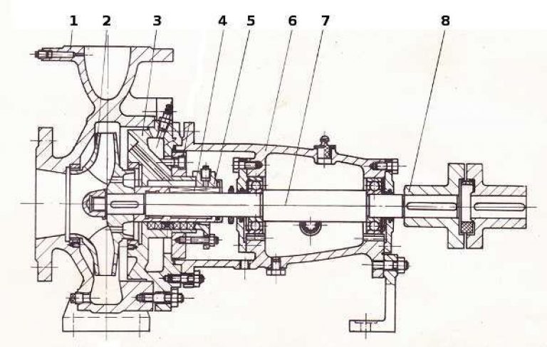
The layout of the pump is presented in the diagram, where it is indicated:
- Case cover.
- Body.
- Sealants.
- Impeller.
- Bearing unit.
- Stuffing box.
- Protective sleeve.
- Stuffing box.
- Shaft of rotation.
- Support bracket.
- Rotation bearing.
In all pumps with a capacity of more than 10 kW there is a drum unloading system from axial forces, it is not provided for in low-power units. Sealing the casing from the inside is ensured by sealing rings (3), which prevent the liquid from passing into the low pressure zone, which increases the overall efficiency of the pump. The rotation shaft is sealed by a stuffing box (8), a protective sleeve (7) is also provided, which prevents shaft abrasion in the contact zone with the packing.
The functional purpose of the pump directly affects the materials used for the manufacture of its spare parts. So, in general industrial equipment impellers of alloy steels are used, less often - of gray cast iron. Pumps for the chemical industry are equipped with drums made of special alloys that are resistant to the effects of the pumped medium.
The unit body can be made of cast iron, steel, aluminum or stainless steel. The material of the sealing rings, seals and seals is selected based on their temperature of the working medium. The most common K-class cantilever pump is designed to work with liquids with temperatures up to 85 0.
1.2 Overview of the console pump K8-18 (video)
2 Marking and selection features
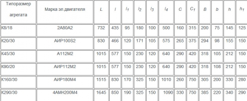
The production of “K” class cantilever pumps is carried out in accordance with the standard GOST No. 22247-96. According to this document, units are classified into 14 sizes according to feed power and pressure. All models are uniformly labeled. type K70-50-220-SD-UHL-3which indicates:
- K - type of equipment (console pump);
- 70 - diameter of the suction pipe (mm);
- 50 - diameter of the supply pipe;
- 220 - the diameter of the blade drum;
- SD - double seal packing (C - single seal);
- UHL - a variant of a climatic modification according to GOST 15150-69;
- 4- category of accommodation.
The choice of a specific model of a consolnik is made according to the catalogs of the manufacturer, which indicate the purpose of the equipment, its design features and technical characteristics. The main selection parameters are power, feed pressure and cavitation reserve.
The cavitational reserve of the system in which the pump will be installed can be calculated by the formula: K \u003d ((p1-p2) / m) - B - Dwhere:
- p1 is the pressure on the surface of the liquid in the tank from which the working medium is taken;
- p2 is the vapor pressure of the liquid in the operating temperature range;
- m is the specific gravity of the working medium;
- B - total pressure loss in the suction channel when operating at maximum performance;
- D - suction height (distance from the pump shaft to the level of the working medium in the storage tank).
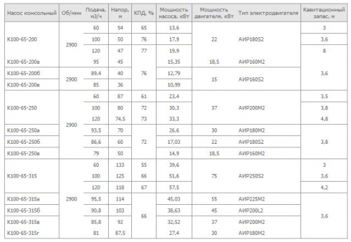
Among the most common equipment in the domestic industry, we distinguish the following brands of pumps:
- To 20/30 - power 4 kW, capacity - 20 m3 / h, head - 30 m, cavitation stock - 3.5 m, weight - 77 kg.
- To 45/30 - power 7.5 kW, productivity - 45 m3 / h, head - 30 m, cavitation stock - 4 m, weight - 158 kg.
- To 160/30 - power 30 kW, productivity - 160 m3 / h, head - 30 m, cavitation stock - 4.2 m, weight - 420 kg.
- K 290/30 - power 37 kW, productivity - 290 m3 / h, head - 30 m, cavitation stock - 4 m, weight - 550 kg
Also, KDN series consoles from the company DAB (Italy) have proven themselves well. The manufacturer's assortment includes single-stage and multi-stage centrifugal pumps with a capacity of 5.5-75 kW, capacity from 12 to 360 m 3 / h and a head of 26-70 m. The cost of equipment starts from 100 thousand rubles.
2.1 Nuances of installation and repair of console pumps
Since konsolniki are quite massive and dimensional equipment, their installation requires the arrangement of the foundation. The concrete base should be 20 cm larger than the dimensions of the pump casing on each side and have a minimum thickness of 20 cm. The pump frame must be rigidly fixed to the foundation with anchors. Between the body and the plate, a vibration-absorbing pad is mandatory.
Suction and delivery pipes must be installed so that no pressure is applied to the pump casing. In this case, the rigid fixation of the pipes should be moved outside the foundation platform, thus reducing the level of vibration acting on them. Shut-off valves must be mounted in front of the pipes on both pump nozzles, and counter-flanges are also required to prevent the pipes and nozzles from undocking due to vibration loads.
Overhaul of the cantilever unit must be carried out after the development of the established resource, which differs depending on the brand of equipment. In the process of operation of the console, the following malfunctions most often occur:
- lack of pressure at startup - the reason may be insufficient filling of the tank with pumped liquid or clogging of the suction line;
- reduced productivity - reasons: impeller wear, increased resistance in the feed pipe;
- fluid leakage through seals and seals - reasons: increased supply pressure, wear of insulating elements;
- drive overload - reasons: supply is higher than permissible, mechanical damage to the motor;
- overheating of bearings - reasons: shaft alignment has shifted, insufficient lubrication;
- strong vibration and noise during operation - reasons: excess cavitation reserve, the unit is not rigidly fixed to the foundation, wear of bearings.
During operation, cantilever pumps require daily maintenance and preventive maintenance, with a frequency of once every 3 months.
The cantilever water pump is a quality and reliable design. It is used for pumping clean cold or hot water, with an acceptable small amount of solid concentrations (up to 0.1% with a maximum size of 0.2 mm). The efficiency of these pumps is 60-80%, depending on the model and power of the electric motor. Cantilever monoblock water pumps have both stuffing box and mechanical seal, the second is the highest quality. The operating temperature with the stuffing box packing should be 0-85 degrees, and with the mechanical seal it is allowed up to 105 degrees. It is strictly forbidden to operate these pumps in industries associated with fire and explosion hazard. And also with their help it is impossible to pump flammable liquids.
Design Features
In most cases, type K centrifugal cantilever pumps are used for pumping water. In their running gear there is a shaft resting on a bearing on which the impeller is located. It is also equipped with a compensation chamber, which avoids possible leaks with high pressure.
The rear and front seals block external and internal leaks. Leaks through the stuffing box are not removed and serve as a lubricant, thereby preventing the engine from overheating. The protective sleeve protects the shaft above the oil seal from wear.
Discharge openings are possible in the impeller disk, which serve to balance the axial force. They are permissible for structures with a capacity of 10 kW or more, since at lower power the axial force is controlled by bearings.
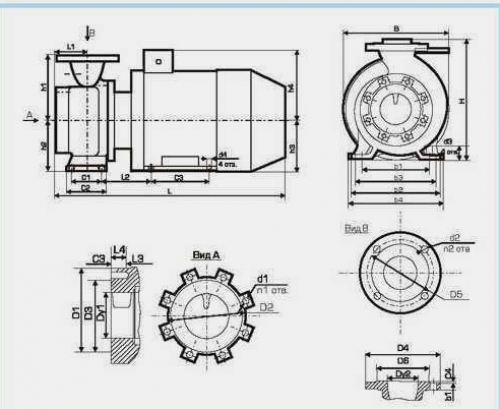
Console pump K device
Console Pump Drawing
1. The cover. 2 building. 3. Replaceable sealing rings. 4. Impeller. 5. Nut. 6. Gland packing. 7. Replaceable sleeve. 8. Packing cap. 9. Val. 10. Support bracket. 11. Ball bearing.
One-piece cantilever pumps are characterized in that the impeller is located at the end of the shaft. These are more powerful designs called “KM” pumps. They are mainly used in production and in enterprises in the engineering system. Having such powerful advantages, this design has a large size, heavy weight and unreliable seal, which requires regular inspection of the pump and timely repair of various malfunctions. Another negative quality of these designs is the complexity and inconvenience of replacing an electric motor. Repair of pumps of the "KM" type is longer, expensive and time consuming than the type "K".
Operating principle
The principle of operation of cantilever pumps is simple, and is determined by design features.
When the electric motor is connected to the network, the impeller blades begin to rotate, due to this there is pressure and water is pumped, thereby entering one hole and leaving the other, which is on the opposite side. The rotation of the impeller makes a great acceleration, contributing to an increase in speed for pumping fluid.
However, too much engine speed leads to a decrease in the pressure of the suction port, which causes cavitation. It is formed in the process of vaporization with further condensation of air in the working fluid. Therefore, you need to choose a console pump with an experienced person.
Calculation and selection of console pumps for water
The selection is carried out using catalogs, which give information about their use and purpose, as well as a description of the design, graphic and technical specifications. In addition, they give drawings indicating the connecting dimensions and dimensions.
The organizations creating the project are recommended to use the catalog only during the technical design, as a new GOST “Centrifugal Console Pumps with Axial Inlet for Water” is being created. When designing for more accurate information, you should contact the manufacturing plants.
When choosing a pump, it is necessary to take into account that the operating mode corresponds to its characteristics. Consider the method of selecting console pumps of type K.
The pump size is selected according to the maximum flow rate. According to the pressure and flow on the graph of Q-H fields, the pump of the right size is pre-selected, and then the right choice is made according to the graphic characteristic.
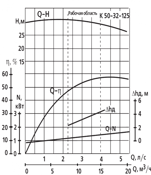
The technical and graphic characteristics determine the desired impeller diameter. The pressure curve for it should pass through a given point of the parameters for pressure and fluid supply, or be higher than it.
When choosing a pump, it is mainly necessary to ensure cavitation operation. Therefore, you should make sure that the selected design in terms of navigational qualities really corresponds to the system for installing the unit.
Cavitational reserve of the system Δ h \u003d ((p a - p t) / γ) - [± H 0] - Σ h b w. Where:
- Pa is the absolute pressure on the surface of the water in the tank, from where the pumping is carried out.
- Pt - saturated vapor pressure when pumping water at operating temperature.
- y is the specific gravity of the pumped water H / m3.
- h b w - total pressure loss of the suction pipe at the required maximum flow.
- H0 - geometric support, or suction height. This value corresponds to the vertical distance of the shaft axis in terms of fluid level from the pumped-out reservoir. It has excellent qualities if the pump is located above the level of the pumped liquid and negative if the pump is installed below the level.
The permissible cavitation margin of the selected pump design Δ h and power is determined by the graphical characteristic, at maximum flow.
The power of the required electric motor Ne is equal to Ne \u003d R N γ / 1OOO.
- R. Safety factor.
- N. Pump power at rated mode, kW.
- y. The specific gravity of the pumped liquid.
Technical characteristics of console pumps and average cost for the most popular models
Console pump K 160/30
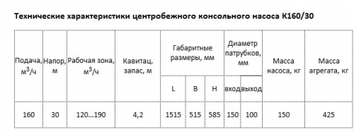
Engine-180M4 30 kW, flow-160 cubic meters, head 30 m, weight-420 kg, price-50 552 00 rub.
Console pump K 290/30
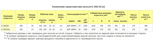
Engine-200M4 37 kW, flow-290 cubic meters per hour, head-30 m, weight-550 kg, price-68 26 rubles
Installation of console pumps
- It is recommended to install the pump on an even and high-quality concrete base, which is able to provide reliable fastening of the purchased pump. The foundation must absorb various vibrations, shocks and linear deformations. The mass of the foundation should be one and a half times the mass of concrete. And its width and length should be one meter more along the perimeter of the supporting frame. The pump is installed in the center of the concrete base and fixed.

- During the installation of pipes, it must be taken into account so that mechanical forces are not transmitted to the pump casing.
- The pressure and suction pipes must be of a suitable size, taking into account the pressure in the pump at the inlet.
- Pipes should be installed without air accumulation, especially in the suction line.
- Shut-off valves must be installed on both sides of the cantilever pump. This is done so that during repair or cleaning, liquid does not leak from the system.
- The suction and pressure pipes must have appropriate fittings. Install them as close as possible to the pump.
- The counter flanges are positioned in relation to the pump flanges so as to remove the voltage from the pump. Otherwise, it can ruin it.
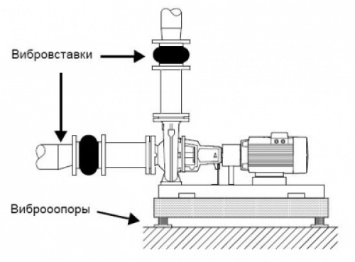
- To achieve excellent cantilever pump operation, vibration and noise must be minimized. To do this, consider methods for eliminating vibration. Such measures are taken during operation of pumps with electric motors, the power of which exceeds 11 kW. However, it should be borne in mind that lower power engines can also contribute to the formation of unwanted vibration and noise.
Various vibrations and noises are caused by the rotation of the rotors and the motor, as well as the flow in the joints and pipes. The most effective means to reduce them are vibration inserts and vibration mounts. To prevent the transmission of vibration to the building, it is necessary to isolate the pump foundation from the house using vibration mounts.
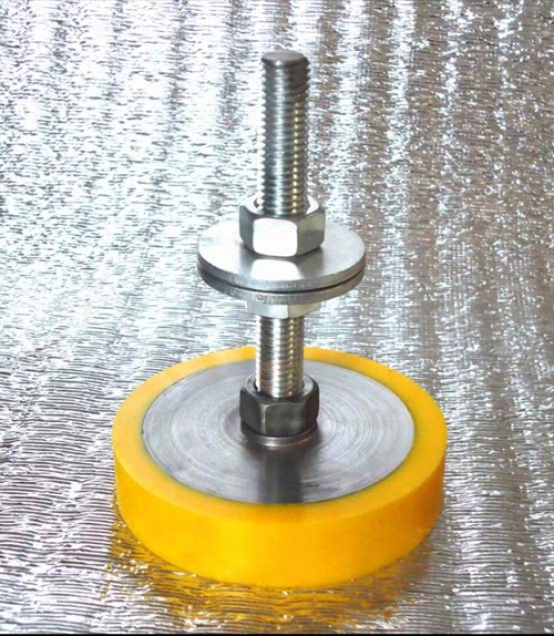
When choosing vibration mounts, the following data should be taken into account: the force that is transmitted along the support, the rotational speed of the electric motor, taking into account the control and the required amount of vibration damping. The amount of blanking is measured in percent, it is desirable that it be at least 70%.
The selection of vibration mounts occurs in different ways, it all depends in what conditions the installation will be performed. In some cases, incorrectly selected vibration mounts may well not only not dampen the vibration, but rather increase its level. Therefore, the choice of vibration mounts should be made by designers.
Vibration insert is an elastic flexible insert, its purpose is to prevent vibrations in piping systems, for example, in pumping equipment. It creates the restoration of thermal elongation within the deformation specified in the technical specifications, and protects the equipment from mechanical stress.
By order, control rods are supplied for flexible vibration inserts, they are used to limit and protect the inserts from deformation. The diameter of the rods must be at least 100 mm.
When installing the pump on a foundation with vibration mounts, always place vibration inserts on the flanges. This is necessary so that during vibration the pump does not hang on them.
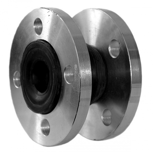
Vibration inserts are installed to suppress compression and expansion in pipelines, which is created by changing the temperature of the liquid. They also reduce the mechanical stress generated in the pipeline by pressure surges and isolate noise. They can not be installed to restore inaccuracies in the pipeline, for example, offset flanges.
It is necessary to fix the vibration insert from the pump at a distance equal to 1-2 nominal diameter of the flange, from the pressure side of the pipe and from the suction pipe. This prevents the presence of turbulent flow in it, creates good suction conditions and causes a slight pressure drop in the pressure pipe.
At a high fluid flow rate, vibroinserts larger should be installed to fit the diameter of the pipeline. If the flanges exceed DN 100, then vibration inserts with restrictive couplers must be used.
Types of console pump repair
There are two types of repair of console pumps: capital and current.
The need for pump repair depends on the operating conditions. Types of repairs and the consumption of spare parts, which is indicated in the technical documentation, is established by the average reliability indicator. For all this, the calculations are made from the conditions of pumping clean liquid by pumps with the amount of suspended particles not exceeding 3 kg / m3. Therefore, the need for repair work for any specific conditions can be very different from the calculated one. There are structural schemes in which the order of various types of repair is displayed.
The structural diagram of the repair cycle of a large-sized console pump has the following form:
Н-Т-Т-Т-Т-Т-К, where Н-start of operation; T-current repair; K-overhaul.
Maintenance made for prevention. It includes the replacement of worn parts and equipment adjustment. In this case, inspect the flow part, measure the gaps between the shaft and the bearing shells of the motor and pump.
Capital- this is a volumetric scheduled repair, it consists in the complete dismantling of the unit, replacement or restoration of parts, adjustment and testing according to the program drawn up by the repair and maintenance documentation.